10
T500 Series Programmable Thermostats Product/Technical Bulletin
W
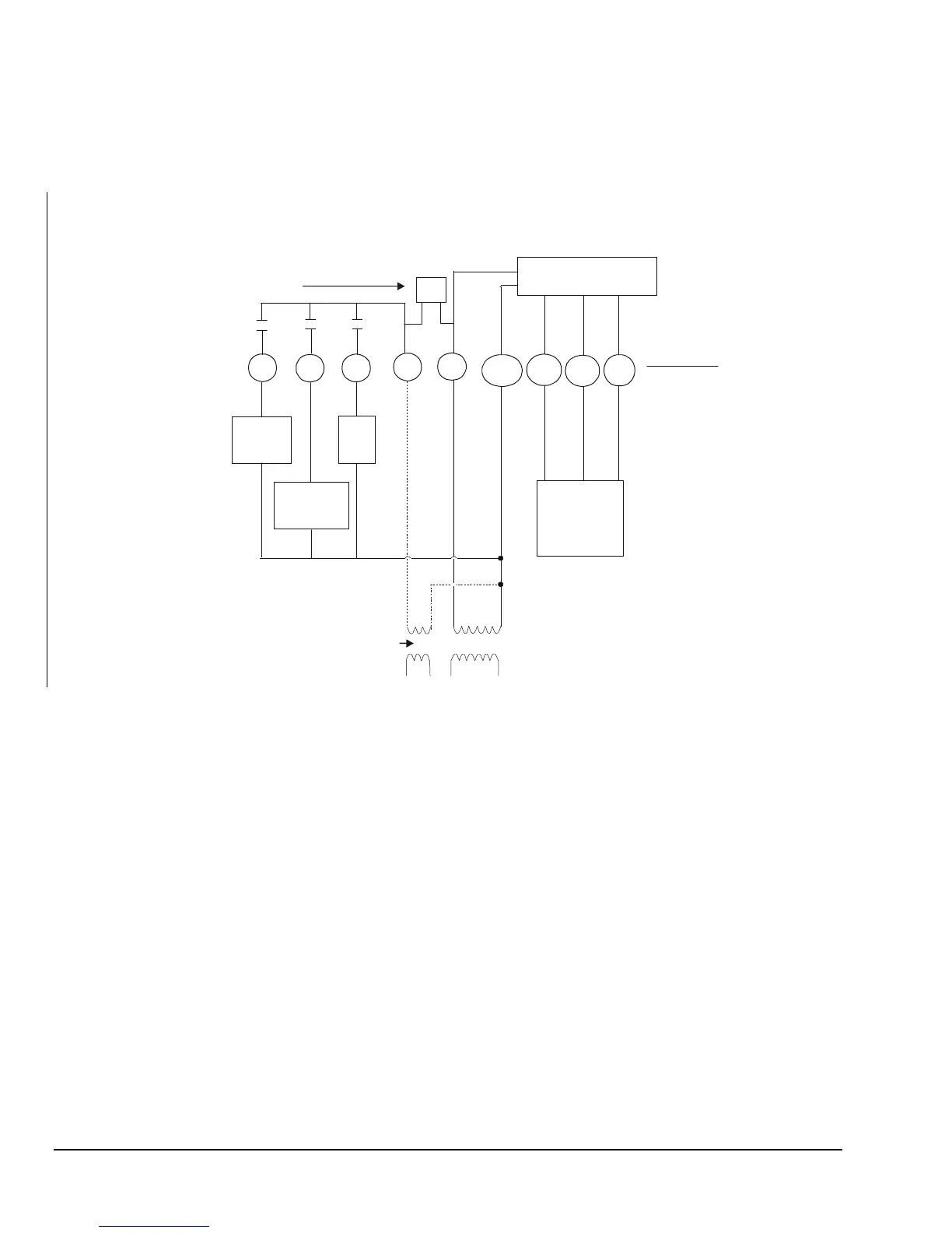
iring Diagrams
1st Stage
Compressor
1st Stage
Heat
Fan
W1
Y1 G
24V(c)
R
24V
T1
T2
RS+V
RS1
RS2
Remote
Sensor
(if used)
Thermostat
Equipment
Electronics
If the transformer (T2) is to power all of the loads,
R and 24 must be connected by inserting jumper J 1
located above the relays. If a separate 24V
transformer (T1) is to be used, remove J 1 to
disconnect R and 24V(c).
P
P
Hcp-1diag
J1P
Optional
Figure 15: T500HCP-1 Wiring Schematic
 Loading...