T500 Series Programmable Thermostats Product/Technical Bulletin
11
1st Stage
Compressor
Reverse
Valve
Heating
2nd Stage
Heat
1st Stage
Heat
Fan
Reverse
Valve
Cooling
W1
Y1 Y2
W2
G
O
B
24V(c)
RS+V
RS1
RS2
Remote
sensor
(if used)
R
24V
LED1
LED2
T1
T2
Field contact switches
2nd Stage
Compressor
Electronics
COM
OCC
(all other
events)
NO NC
COM
UNOCC
(night event
if
thermostat
loses power)
NO
NC
Thermostat
Equipment
Hpp-1diag
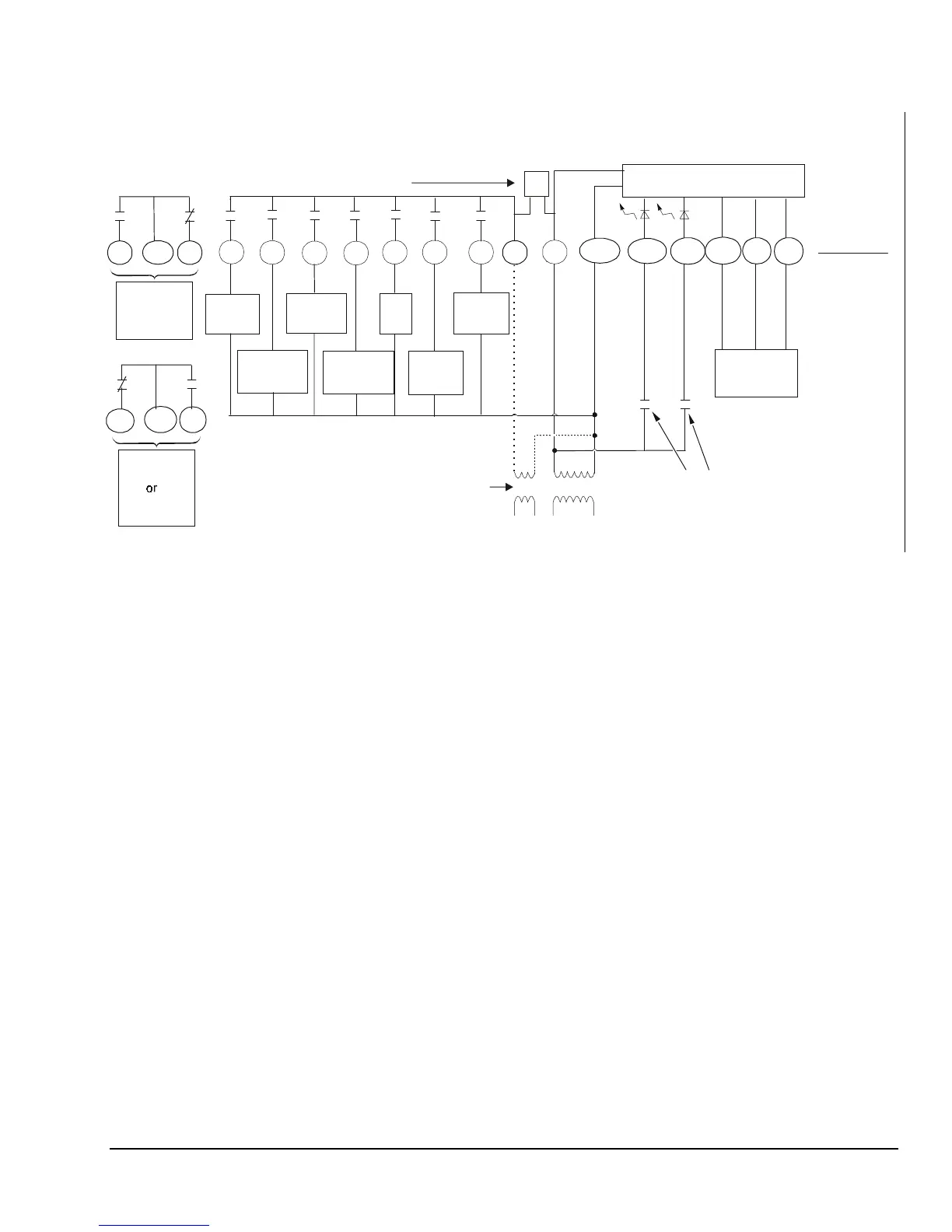
If the transformer (T2) is to power all of the loads
R and 24V must be connected by inserting jumper
1, located above the relays. If a separate 24V
transformer (T1) is to be used, remove the jumper
to disconnect R and 24V.
JP
JP1
JP1
Optional
Figure 16: T500HPP-1 Wiring Schematic
 Loading...