12
T500 Series Programmable Thermostats Product/Technical Bulletin
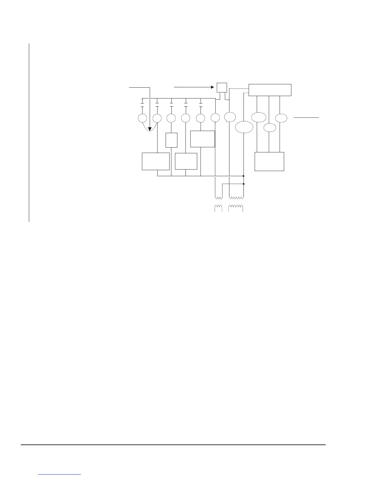
Compressor
Fan
W1
Y1
G
24V(c)
R
24V
T1 T2
RS+V
RS1
RS2
Remote
sensor
(if used)
Electronics
O B
Reverse
Valve
Cooling
Reverse
Valve
Heating
Thermostat
Equipment
Single-Stage Heat Pump:
Leave the factory-installed jumper
connected between W1 and Y1 and
wire O or B as shown.
Conventional Single-Stage Heat/Cool:
between W1 and Y1 and wire as shown
in Figure 12. Note that the O and B terminals
are not used in this application.
If the transformer (T2) is to power all of the
loads, R and 24V must be connected by
inserting jumper JP1, located above the
relays. If a separate 24V transformer (T1)
is to be used, remove the jumper JP1 to
disconnect R and 24V(c).
JP1
Hpp2-diag
Remove the factory-installed jumper
Figure 17: T500HPP-2 Wiring Schematic
 Loading...