T600HCx-3 Single-Stage Thermostats Installation Instructions 3
Wiring
When an existing thermostat is replaced, remove and
label the wires to identify the terminal functions. When
a T600HCx-3 thermostat is replaced, simply remove
the old screw terminal blocks and reinsert them onto
the PCB of the replacement thermostat.
To wire the thermostat:
1. Strip the ends of each wire a 1/4 in. (6 mm) and
connect them to the appropriate screw terminals as
indicated in Figure 5.
2. Carefully push any excess wire back into the wall.
Seal the hole in the wall with fireproof material to
prevent drafts from affecting the ambient
temperature readings.
3. Reinsert the screw terminal blocks onto the PCB.
4. Reattach the thermostat cover to the mounting
base (top side first).
5. Use a Phillips-head screwdriver to reinstall the
security screw on the bottom of the thermostat
cover.
CAUTION: Risk of Electric Shock.
Disconnect the power supply before
making electrical connections to avoid
electric shock.
MISE EN GARDE : Risque de décharge
électrique.
Débrancher l'alimentation avant de
réaliser tout raccordement électrique afin
d'éviter tout risque de décharge
électrique.
CAUTION: Risk of Property Damage.
Do not apply power to the system before
checking all wiring connections. Short
circuited or improperly connected wires
may result in permanent damage to the
equipment.
MISE EN GARDE : Risque de dégâts
matériels.
Ne pas mettre le système sous tension
avant d'avoir vérifié tous les raccords de
câblage. Des fils formant un court-circuit
ou connectés de façon incorrecte
risquent d'endommager
irrémédiablement l'équipement.
IMPORTANT: Make all wiring connections in
accordance with local, national, and regional
regulations. Do not exceed the electrical ratings of
the T600HCx-3 thermostat.
Figure 5: Terminal Blocks
4 pole left top connector
2 pole right top connector
RH W1
RS
Scom
6 pole bottom connector
OS
MS
AUX
2
34
56
7
10 11 12 14
15
1613
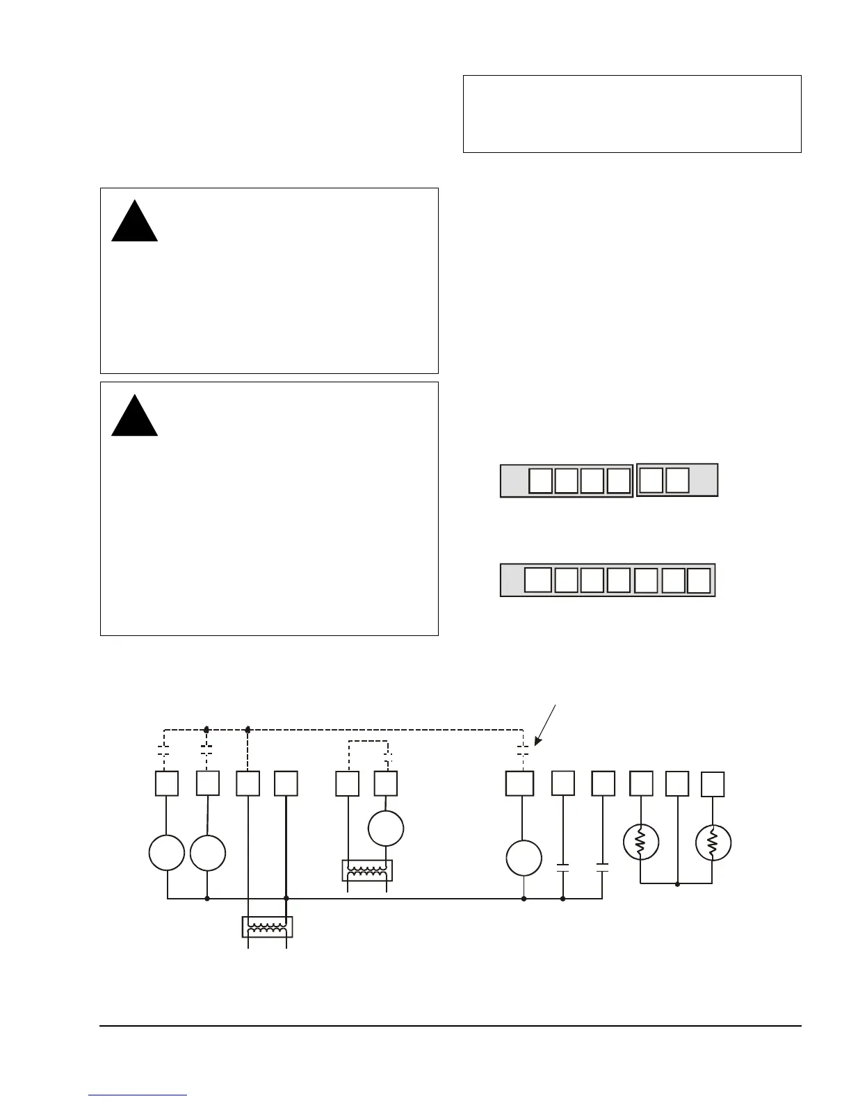
Figure 6: Wiring the T600HCx-3 Thermostats
Cool 1
Fan
24 VAC
Thermostat Power
Heat 1
Y1
GRCC
RH W1
AUX
D1
D2
Scom
Aux
If using the same power source
for the thermostat and heating
loads, install a jumper
across RC and RH.
Remote
Outdoor
OS
F
I
G
:
T
6
0
0
H
C
P
_
w
i
r
Isolated Contact
- On/Off Actuation