T600HPx-4 and T600HPx-4+PIR Series Heat Pump Thermostat Controllers Installation Instructions2
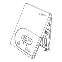
Note: PIR models have a wiring connection between
the cover and the Printed Circuit Board (PCB). This
connection allows for proper wiring of the occupancy
sensor. Carefully remove the wiring connection from
the PCB by pulling up on the connector block. Do not
attempt to remove the connector block by pulling on the
wires.
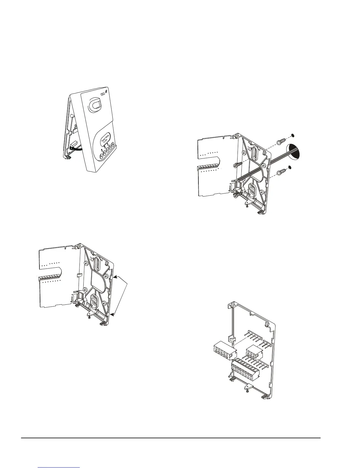
3. Carefully pull the locking tabs on the right side of
the thermostat controller mounting base and
unlock the PCB. Open the PCB to the left as
illustrated in Figure 2.
4. Pull approximately 6 in. (152 mm) of wire from the
wall and insert the wire through the hole in the
thermostat controller mounting base.
5. Align the thermostat controller mounting base on
the wall and use the base as a template to mark
the two mounting hole locations.
Note: Be sure to position the thermostat controller
mounting base so that the arrow on the base points
upward to indicate the top of the thermostat controller.
6. Drill a 3/16 in. (5 mm) hole at each of the two
marked locations and tap nylon anchors (included
with the thermostat controller) flush to the wall
surface.
Note: Other means of anchoring the device may be
desired, depending on the wall medium.
7. Position the thermostat controller mounting base
on the wall and use the two mounting screws
(included with the thermostat controller) to secure
the base to the wall surface as illustrated in
Figure 3.
Note: Be careful not to overtighten the mounting
screws.
8. Swing the PCB back to the right and carefully snap
it into the locking tabs on the thermostat controller
mounting base.
9. Remove the screw terminal blocks that are
attached to a disposable adhesive. Figure 4
illustrates the locations of the screw terminal
blocks on the thermostat controller.
Figure 1: Removing the
Thermostat Controller Cover
(T600HPx-4+PIR Model Shown)
Figure 2: Opening the
Thermostat Controller PCB
PCB
Locking
Figure 3: Securing the Thermostat Controller
Mounting Base to the Wall
Figure 4: Removing the Screw Terminal Blocks
F
I
G
:
t
r
m
n
l
_
b
l
c
k
s