T600HPx-4 and T600HPx-4+PIR Series Heat Pump Thermostat Controllers Installation Instructions 3
Wiring
When an existing thermostat controller is replaced,
remove and label the wires to identify the terminal
functions. When a T600HPx-4 or T600HPx-4+PIR
Series Thermostat Controller is replaced, simply
remove the old screw terminal blocks and reinsert them
onto the PCB of the replacement thermostat controller.
To wire the thermostat controller:
1. Strip the ends of each wire a 1/4 in. (6 mm) and
connect them to the appropriate screw terminals as
indicated in Figure 5.
2. Carefully push any excess wire back into the wall.
Note: Seal the hole in the wall with fireproof material
to prevent drafts from affecting the ambient
temperature readings.
3. Reinsert the screw terminal blocks onto the PCB.
Note: If multiple wires are inserted into the terminals,
be sure to properly twist the wires together prior to
inserting them into the terminal connectors.
4. For PIR models, carefully reattach the PIR
connector to the PCB.
5. Reattach the thermostat controller cover to the
mounting base (top side first).
6. Use a Phillips-head screwdriver to install the
security screw on the bottom of the thermostat
controller cover if desired. The security screw
comes packaged separately in a plastic bag with
the thermostat controller.
CAUTION: Risk of Electric Shock.
Disconnect power supply before making
electrical connections to avoid electric
shock.
CAUTION: Risk of Property Damage.
Do not apply power to the system before
checking all wiring connections. Short
circuited or improperly connected wires
may result in permanent damage to the
equipment.
IMPORTANT: Make all wiring connections in
accordance with local, national, and regional
regulations. Do not exceed the electrical ratings of
the T600HPx-4 or T600HPx-4+PIR Series
Thermostat Controller.
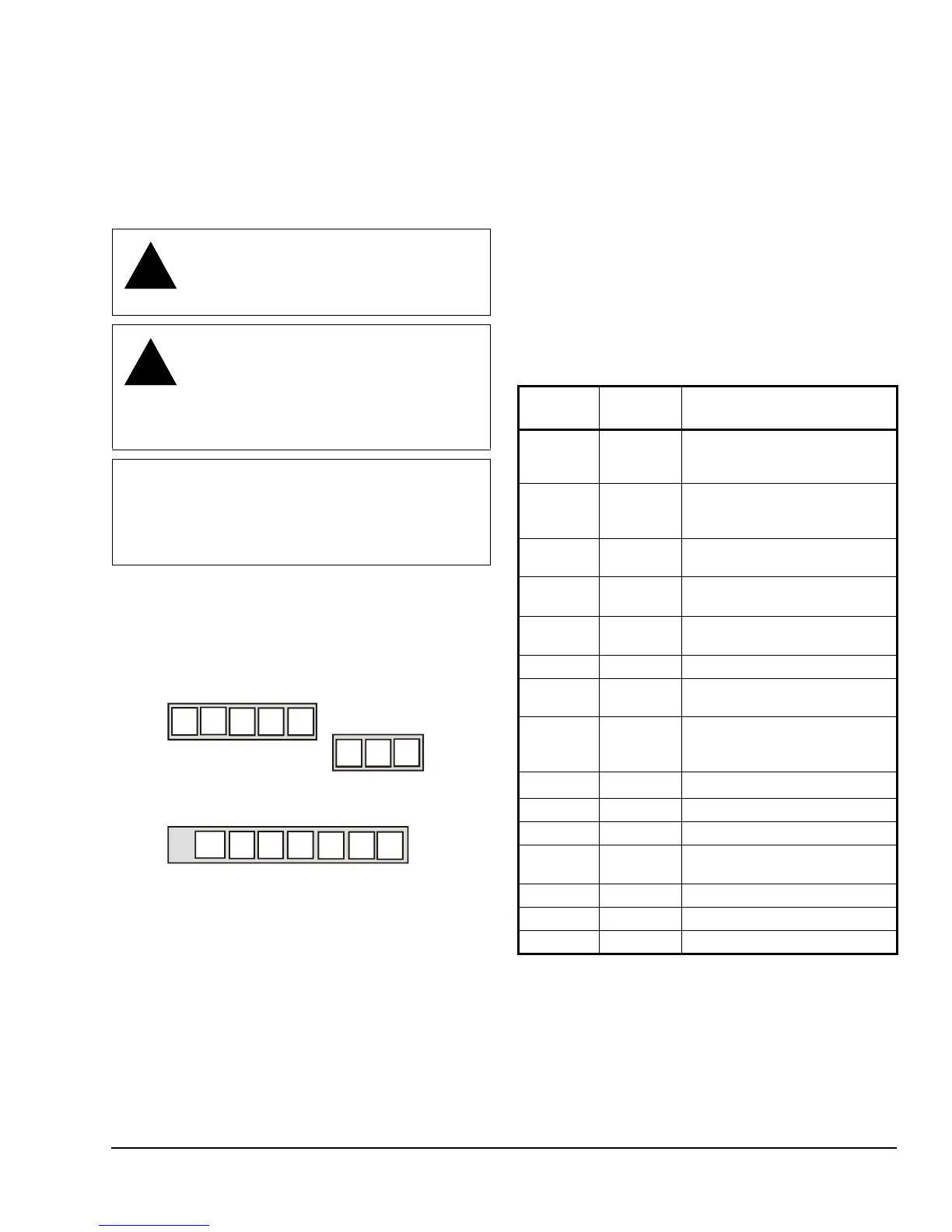
Figure 5: Terminal Blocks
Five-Pole
Left Top Connector
Three-Pole
RH
DI1 DI2
Scom
Seven-Pole Bottom Connector
10 11 12 14
15
1613
O/B
Table 1: Terminal Identification (See Figure 5.)
Terminal
Number
Terminal
Label
Function
1
Y2
1
1. This terminal provides the voltage from RC through a
relay contact.
Energizes Second-Stage
Compressor on a Call for
Heating or Cooling
2
Y1
1
Energizes First-Stage
Compressor on a Call for
Heating or Cooling
3
G
1
Energizes Fan in Accordance
with Selected Fan Mode
4 RC 24 VAC from Equipment
Transformer
5 C 24 VAC (Common) from
Equipment Transformer
6 RH 24 VAC for Auxiliary Heating
7
W1
2
2. This terminal provides the voltage from RH through a
relay contact.
Energizes on a Call for Auxiliary
Heating
8 O/B Reversing Valve; Energizes a
Valve on a Call for Heating or
Cooling
10
AUX
1
Auxiliary Output
11 DI1 Configurable Digital Input 1
12 DI2 Configurable Digital Input 2
13 RS Remote Room Temperature
Sensor
14 Scom Sensor Common
15 OS Outside Air Temperature Sensor
16 MS Not Used