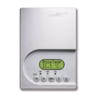
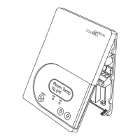
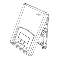
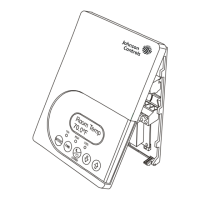
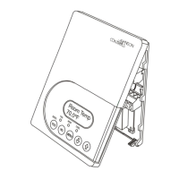
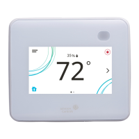
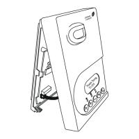
TEC2604-4 and TEC2604-4+PIR BACnet® MS/TP Networked Multi-Stage Economizer Thermostat
Controllers Installation Instructions
16
Technical Specifications
Thermostat Does
Not Come Online
See the probable causes listed previously in the Multiple Symptoms section of this table.
A thermostat controller may be connected to the wrong bus.
A baud rate may be specified in the new thermostat controller that is incompatible with the running
network.
No device on the network is configured to use a specific baud rate (normally the NAE), but all devices
are set to use auto baud. At least one device, typically the bus supervisor (NAE), must have an
assigned baud rate. Set the baud rate in the bus supervisor and set all other devices to auto baud.
1. For common MS/TP troubleshooting information, refer to the
MS/TP Communications Bus Technical Bulletin
(LIT-12011034).
Table 5: Troubleshooting Details
1
(Part 2 of 2)
Symptom Probable Causes
TEC2604-4 and TEC2604-4+PIR BACnet MS/TP Networked Multi-Stage Economizer Thermostat
Controllers (Part 1 of 2)
Power Requirements 19 to 30 VAC, 50/60 Hz, 2 VA (Terminals RC and C) at 24 VAC Nominal, Class 2 or
Safety Extra-Low Voltage (SELV)
Relay Contact Rating (Y1, Y2, G, W1,
W2, and AUX)
19 to 30 VAC, 1.0 A Maximum, 15 mA Minimum, 3.0 A Inrush, Class 2 or SELV
Digital Inputs Voltage-Free Contacts across Terminal C to Terminals DI1 and DI2
Analog Inputs Resistive Inputs (RS and UI3) for 10k ohm Johnson Controls Type II Negative
Temperature Coefficient (NTC) Thermistor Sensors
Wire Size 18 AWG (1.0 mm Diameter) Maximum, 22 AWG (0.6 mm Diameter) Recommended
Temperature Sensor Type Local 10k ohm Johnson Controls Type II Negative Temperature Coefficient (NTC)
Thermistor Sensor
Temperature Range Backlit
Display
-40.0°F/-40.0°C to 122.0°F/ 50.0°C in 0.5° Increments
Heating
Control
40.0°F/4.5°C to 90.0°F/32.0°C
Cooling
Control
54.0°F/12.0°C to 100.0°F/38.0°C
Accuracy Temperature ±0.9F°/±0.5C° at 70.0°F/21.0°C Typical Calibrated
Minimum Deadband 2F°/1C° between Heating and Cooling
Ambient Conditions Operating 32 to 122°F (0 to 50°C); 95% RH Maximum, Noncondensing
Storage -22 to 122°F (-30 to 50°C); 95% RH Maximum, Noncondensing