Table 5: Communication Bus and Supply Power Terminal Blocks, Functions, Ratings, Requirements, and
Cables
Recommended Cable Type
1
Function, Electrical
Ratings/Requirements
Terminal LabelsTerminal Block/Port Label
24 AWG 3-pair CAT 3 Cable
<30.5m (100 ft)
RJ-12 6-Position Modular Port
provides SA Bus Communications
SA Bus provides 15 VDC Power for:
• NS Series Sensors
• Wireless ZigBee WRZ-78xx
Series One-to-One Wireless
Receiver
• Wireless Bluetooth
Commissioning Converter
(BTCVT)
• DIS1710 Local Controller Display
• VAV Balancing Tool
SA BUS
SA BUS
2
0.8 mm to 1.0 mm
(20 to 18 AWG) 2-wire
24 VAC Power Supply - Hot
Supplies 20–30 VAC (Nominal
24VAC)
HOT24~
24 VAC Power Supply Common
The -0 models isolate this terminal
from all other commons.
The -1 models only isolate this
terminal from the FC bus common.
COM
1
See Table 4 to determine wire size and cable lengths for cables other than the recommended cables.
2 The SA Bus and FC Bus wiring recommendations in this table are for MS/TP Bus communications at 38.4k baud. For more
information, refer to the MS/TP Communications Bus Technical Bulletin (LIT-12011034).
Setup and Adjustments
Important: Electrostatic discharge can damage
controller components. Use proper
electrostatic discharge precautions during
installation, setup, and servicing to avoid
damaging the controller.
Setting the Device Address
Metasys® field controllers are master devices on
BACnet® MSTP (SA or FC) Buses. Before operating field
controllers on a bus, you must set a valid and unique
device address for each controller on the bus.
Set a field controller’s device address by setting the
positions of the switches on the Device Address DIP
switch block at the top of the controller (Figure 2). Device
addresses 4 through 127 are the valid addresses for
these controllers.
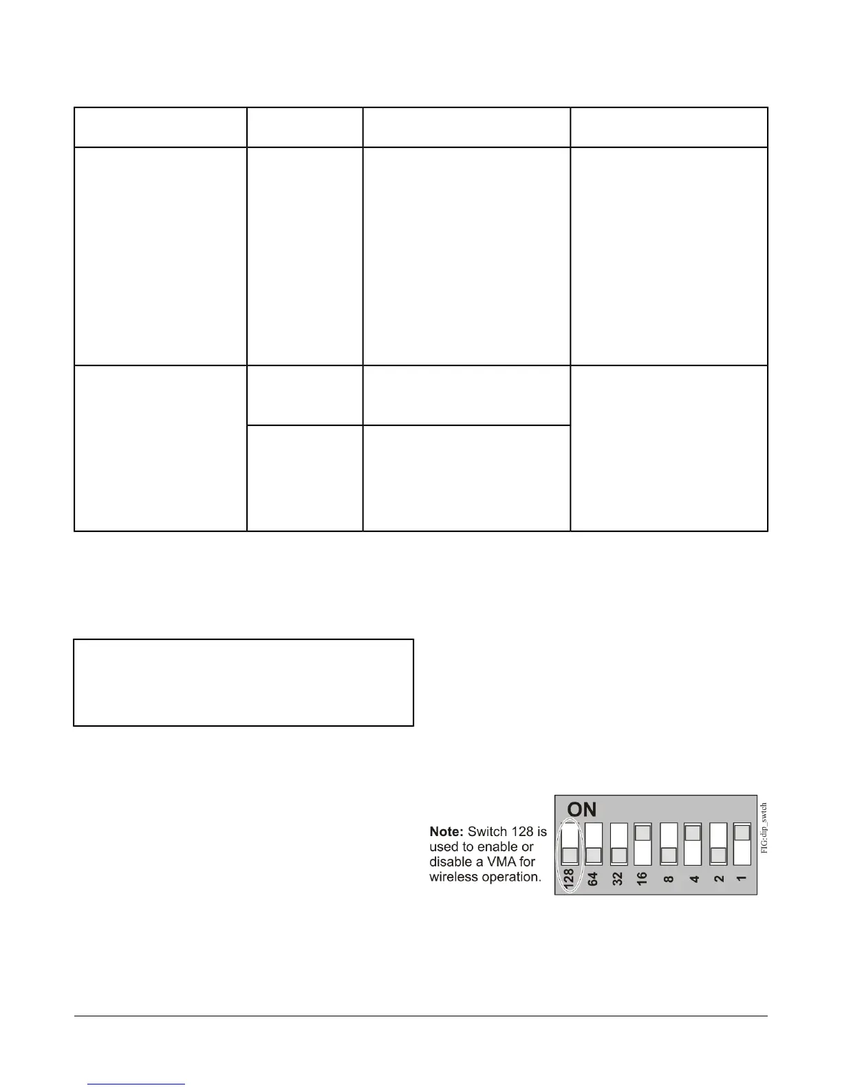
The DIP switch block (Figure 9) has eight switches
numbered 128, 64, 32, 16, 8, 4, 2, and 1. Switches 64
through 1 are device address switches. Switch 128 is a
mode switch that enables a field controller to operate on
a ZFR /ZFR Pro Series Wireless Field Bus. Switch 128
must be set to OFF for all hard-wired SA and FC Bus
applications. Set Switch 128 to ON for wireless FC Bus
applications only.
Figure 9: Device Address Switches Set to 21
15VMA1615/1626/1628/1630 VAV Controllers Installation Instructions
 Loading...


