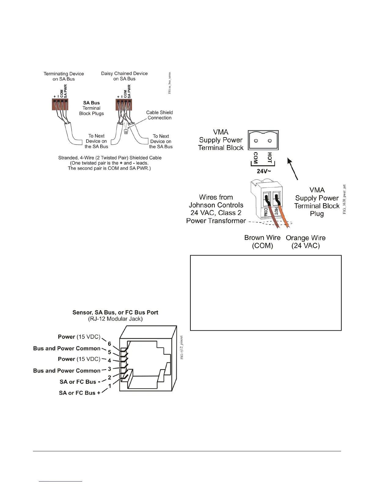
Figure 4: SA Bus Terminal Block Wiring
Modular Ports
The modular and FC Bus ports on the face of the VMA
(Figure 2) are RJ-12 (6-position) modular jacks as shown
in Figure 5.
The modular SA Bus port provides a connection for the
Wireless Commissioning Converter (BTCVT), VAV
Balancing Tool, DIS1710 Local Controller Display,
WRZ78xx Series One-to-One Wireless Transmitter, and
NS Series sensors. The modular FC Bus port provides
a connection for the Wireless Commissioning Converter
and the ZFR/ZFR Pro Wireless Router.
Figure 5: Pin Number Assignments for Sensor (SA
Bus and FC Bus) Ports on VMA1615/1626/1628/1630
Controllers
Note: Do not use the modular SA Bus port and the
terminal block SA Bus simultaneously. Only use
one of these connections at a time.
Supply Power Terminal Block
The 24 VAC supply power terminal block is a gray,
removable, 2-terminal plug that fits into a board-mounted
jack on the upper left of the VMA controller.
Wire the 24 VAC supply power wires from the transformer
to the HOT and COM terminals on the terminal plug as
shown in Figure 6. See Table 5 for more information.
Figure 6: 24 VAC Supply Power Terminal Block Wiring
Important: Exercise caution while rewiring the power
plug when replacing a VMA1610 or
VMA1620 controller. The supply power
terminal on a new VMA is a two-position
terminal block (Figure 6). A VMA1610 or
VMA1620 controller uses a three-position
terminal block, and the center position is
not used. Stray wire strands may make
contact and cause a short circuit across the
24 VAC power supply.
The supply power wire colors may be different on
transformers from other manufacturers. Refer to the
transformer manufacturer’s instructions and the project
installation drawings for wiring details.
7VMA1615/1626/1628/1630 VAV Controllers Installation Instructions
 Loading...


