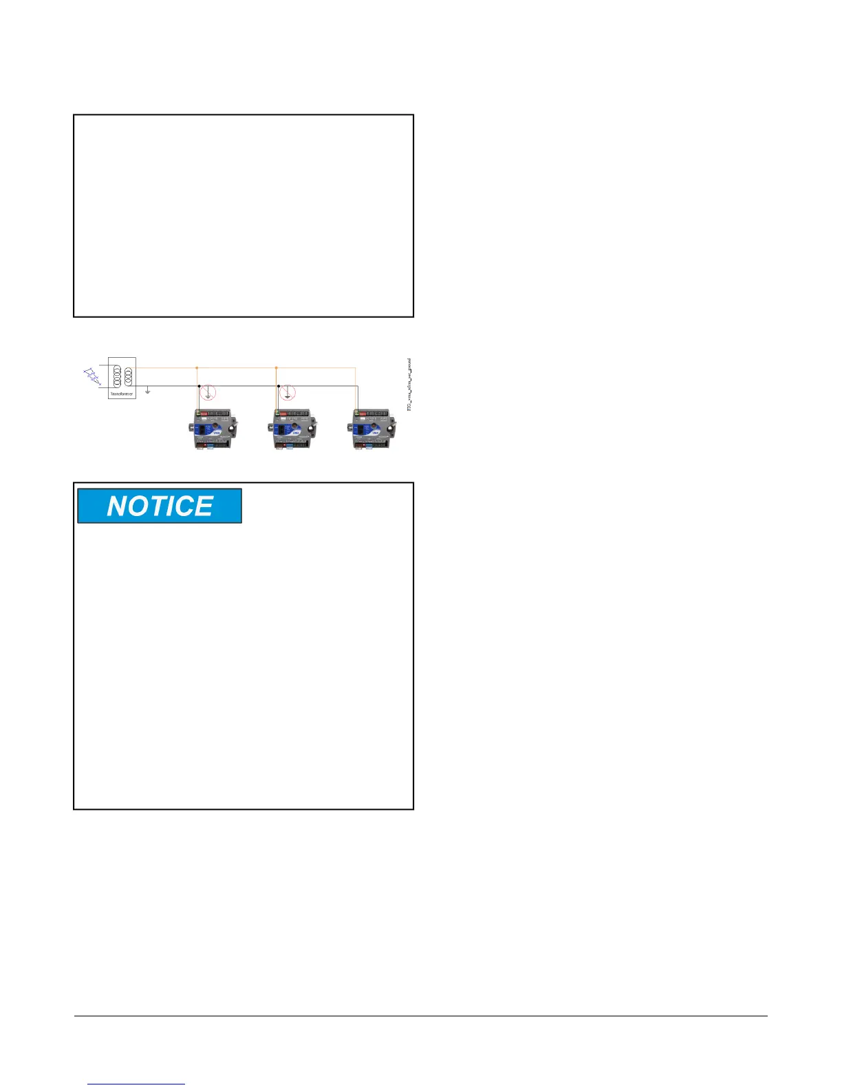
Important: Connect 24 VAC supply power to the VMA
and all other network devices so that
transformer phasing is uniform across the
network devices. Powering network devices
with uniform 24 VAC supply power phasing
reduces noise, interference, and ground
loop problems. The VMA does not require
an earth ground connection. However, when
grounding the secondary of the 24 VAC
transformer is required, only one connection
to ground should be made near the
transformer. See the following figure.
Figure 7: Transformer Grounding
Risk of Property Damage: Do not apply power to the
system before checking all wiring connections. Improper
wiring of this terminal may cause a short circuit across
the 24 VAC power supply on -1 VMA models. A short
circuit may result in a tripped circuit breaker or blown
fuse. If using a transformer with a built-in fuse, the
transformer may need to be replaced.
Risque de dommages matériels: Ne mettez pas
l’appareil sous tension avant d’avoir vérifié toutes les
connexions du câblage. Le câblage inadéquat de cette
borne peut causer un court-circuit sur l’alimentation
électrique de 24 V c.a. des -1 VMA modèles. Un
court-circuit peut causer le déclenchement du disjoncteur
ou le grillage d’un fusible. Si vous utilisez un
transformateur avec un fusible intégré, vous pourriez
devoir remplacer le transformateur.
To wire the VMA1615/1626/1628/1630 controller:
1. Terminate wiring according the appropriate figure in
Termination Diagrams.
2. Wire network sensors and other devices to the VMA's
SA Bus.
3. Wire the FC Bus in a daisy chain.
4. Ensure that the VMA’s device address DIP switches
are set to the appropriate device address. (See
Setting the Device Address.) Also, activate the
end-of-line (EOL) switch if necessary.
5. Connect the VMA controller to 24 VAC, Class 2
power.
Note: If you are using the VMA1615/1626/1628/1630
controller with the Wireless Field Bus System,
refer to the WNC1800/ZFR182x Pro Series
Wireless Field Bus System Bulletin
(LIT-12012320) or the ZFR1800 Series Wireless
Field Bus System Bulletin (LIT-12011336)
VMA Terminal Functions, Ratings,
Requirements, and Wiring Guidelines
Input and Output Wiring Guidelines
Table 3 provides information about the functions, ratings,
and requirements for the VMA input and output terminals,
and Table 4 provides guidelines for wire sizes and cable
lengths.
In addition to the wiring guidelines in Table 3, observe
these guidelines when wiring VMA inputs and outputs:
• Run all low-voltage wiring and cables separate from
high-voltage wiring.
• All input and output cables, regardless of wire size or
number of wires, should consist of twisted, insulated,
and stranded copper wires.
• Shielded cable is not required for input or output
cables but is recommended for input and output
cables that are exposed to high electromagnetic or
radio frequency noise.
• Cable runs of less than 30 m (100 ft) typically do not
require an offset in the input/output software setup.
• Cable runs over 30 m (100 ft) may require an offset
in the input/output software setup.
Maximum Cable Length versus Load Current
Use Figure 8 to estimate the maximum cable length
relative to the wire size and the load current (in mA) when
wiring inputs and outputs.
8VMA1615/1626/1628/1630 VAV Controllers Installation Instructions
 Loading...


