Wiring
Risk of Electric Shock. Disconnect the power supply
before making electrical connections to avoid electric
shock.
Risque de décharge électrique. Débrancher
l'alimentation avant de réaliser tout raccordement
électrique afin d'éviter tout risque de décharge électrique.
Important: Do not connect supply power to the
controller before finishing wiring and
checking all wiring connections. Short
circuits or improperly connected wires can
result in damage to the controller and void
any warranty.
Important: Do not exceed the controller electrical
ratings. Exceeding controller electrical
ratings can result in permanent damage to
the controller and void any warranty.
Important: Use copper conductors only. Make all wiring
in accordance with local, national, and
regional regulations.
Important: Electrostatic discharge can damage
controller components. Use proper
electrostatic discharge precautions during
installation, setup, and servicing to avoid
damaging the controller.
For detailed information on configuring and wiring an
Master-Slave/Token-Passing (MS/TP) Bus, Field
Controller (FC), or Sensor/Actuator (SA) Bus, refer to the
MS/TP Communications Bus Technical Bulletin
(LIT-12011034).
VMA Terminals and Bus Ports
See for input and output terminal and bus port locations
on the VMA1615/1626/1628/1630 controllers. Observe
the following guidelines when wiring a VMA controller.
Input and Output Terminals
The input spade terminals are located on the side of the
VMA near the FC Bus terminal block. The output spade
terminals are located on the opposite side of the controller
near the power supply terminal block. See Table 3 for
more information.
FC Bus Terminal Block (Or N2 Protocol As
Required)
The FC Bus terminal block is a blue, removable,
4-terminal plug that fits into a board-mounted jack.
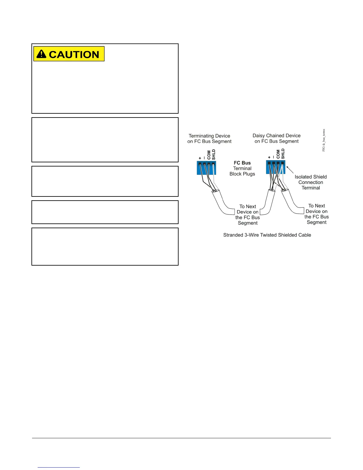
Wire the removable FC Bus terminal block plugs on the
VMA and other controllers in a daisy-chain configuration
using 3-wire twisted, shielded cable as shown in Figure
3. See Table 5 for more information.
Figure 3: FC Bus Terminal Block Wiring
Note: The Shield terminal (SHLD) on the FC Bus
terminal block is isolated and can be used to
connect the cable shields on the bus (Figure 3).
SA Bus Terminal Block
The SA Bus terminal block is a brown, removable,
4-terminal plug with +15 VDC that fits into a
board-mounted jack.
Wire the removable SA Bus terminal block plugs on the
VMA and other SA Bus devices in a daisy-chain
configuration using 4-wire twisted, shielded cable as
shown in Figure 4. See Table 5 for more information.
6VMA1615/1626/1628/1630 VAV Controllers Installation Instructions
 Loading...


