FC and SA Bus and Supply Power Wiring
Guidelines
Table 5 provides information about terminal block
functions, ratings, and requirements.
Table 5 also provides wire size, cable type, and cable
length guidelines for wiring the VMA communication
buses and supply power.
In addition to the guidelines in Table 5, observe these
guidelines when wiring the SA/FC Buses and supply
power:
• Run all low-voltage wiring and cables separate from
high-voltage wiring.
• All FC and SA Bus cables, regardless of wire size,
should be twisted, insulated, stranded copper wire.
• Shielded cable is strongly recommended for all FC
and SA Bus cables.
•
Refer to the MS/TP Communications Bus Technical
Bulletin (LIT-12011670) for detailed information
regarding wire size and cable length requirements for
the FC and SA Buses.
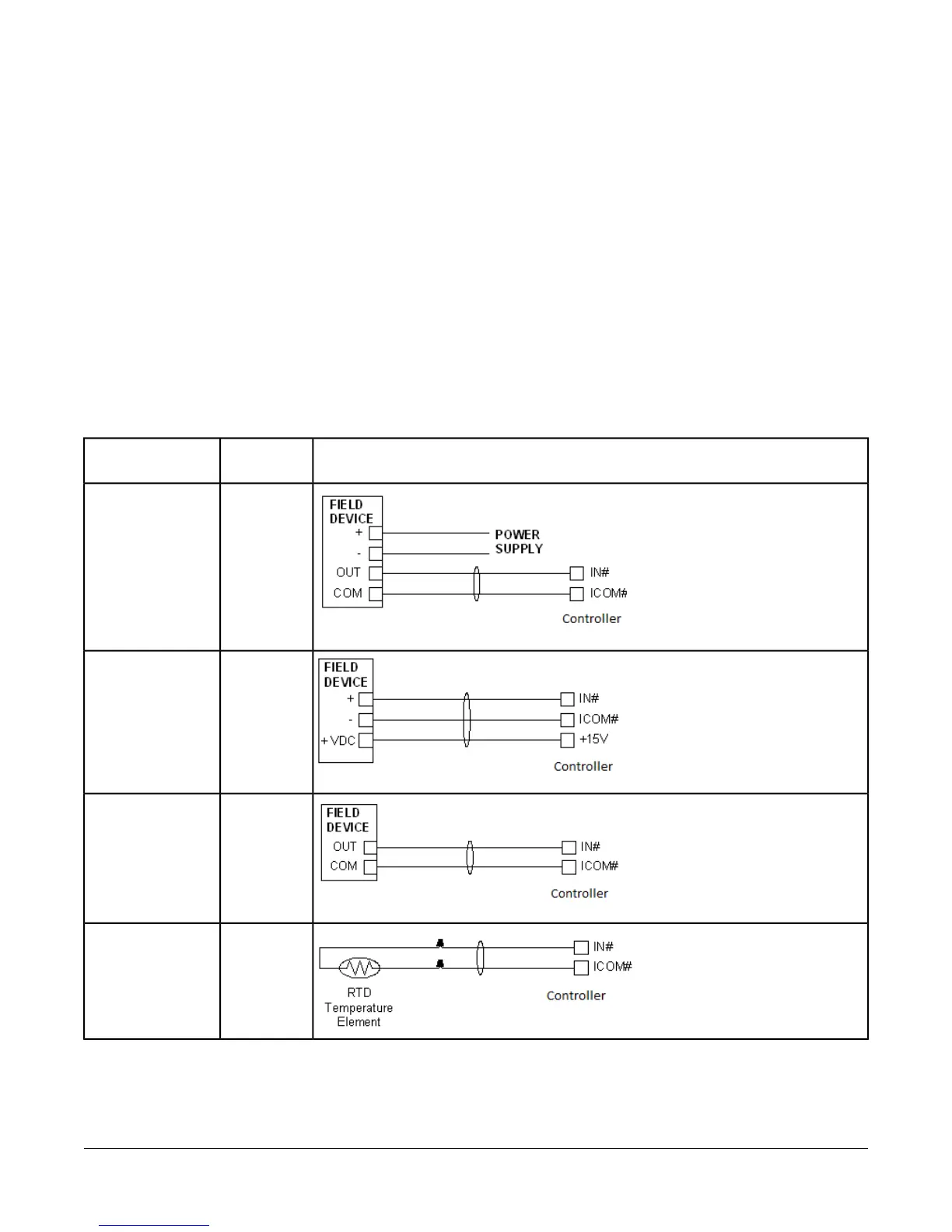
Termination Diagrams
A set of Johnson Controls® termination diagrams provides details for wiring inputs and outputs to the controllers.
See the figures in this section for the applicable termination diagrams.
Table 2: Termination Details
Termination DiagramsType of
Input/Output
Type of Field
Device
UIVoltage Input -
External Source
UIVoltage Input -
Internal Source
UIVoltage Input
(Self-Powered)
UITemperature
Sensor
9VMA1615/1626/1628/1630 VAV Controllers Installation Instructions
 Loading...


