Notes:
• Prior to performing this procedure, be sure the
controller has been converted from BACnet to N2
protocol first. Refer to the Modernization Guide for
Legacy N2 Controllers (LIT-12012005) for more
information.
• This special configuration is required because
controller addresses above 127 were originally
intended for use with the Wireless Field Bus system.
1. Disconnect the 24 VAC supply from the controller.
2. Remove the FC Bus connector from the controller.
3. Set the address switch set to the desired N2 address.
4. Set the address switch segment labeled 128 to OFF.
5. Reconnect the 24 VAC supply to the controller.
6. Using an SA bus connection, download the firmware
and controller application file. The download process
asks to confirm switching the communication protocol
to N2.
7. Click OK.
8. After the download is finished, disconnect the 24
VAC supply to the controller.
9. Set the address switch segment labeled 128 to ON.
10. Reattach the FC Bus connector to the controller.
11. Reconnect the 24 VAC supply to the controller.
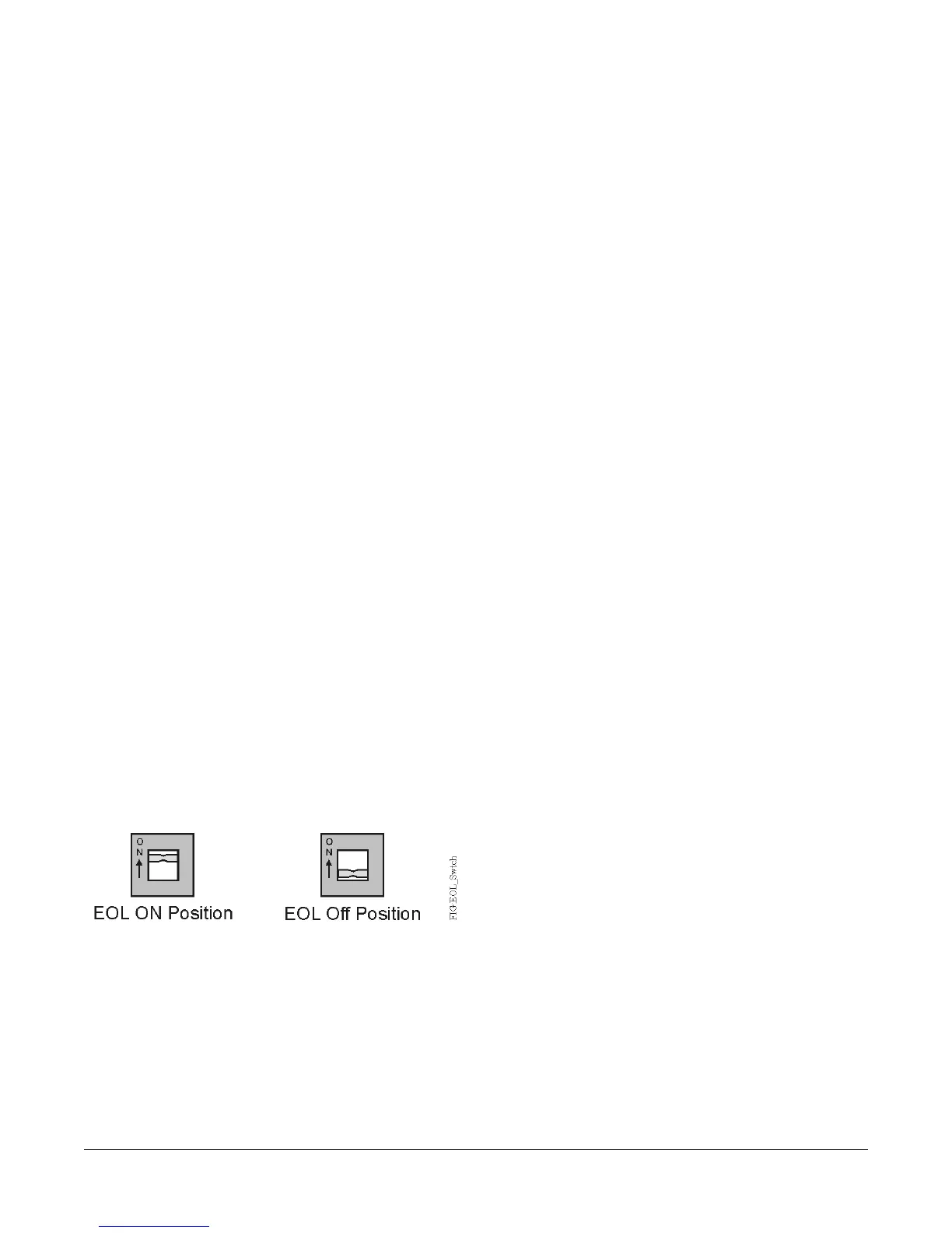
Setting the EOL Switch
Each field controller has an EOL switch, which, when set
to ON (up), sets the field controller as a terminating device
on the bus. See Figure 2 for the EOL switch location on
the field controller. The default EOL switch position is
OFF (down). The amber EOL LED illuminates to show
the EOL is active.
Figure 10: EOL Switch Positions
To set the EOL switch on a field controller:
1. Determine the physical location of the controller on
the SA or FC Bus.
2. Determine if the controller must be set as a
terminating device on the bus.
Note: The EOL termination rules for SA Buses and
FC Buses are different. Refer to the MSTP
Communications Bus Technical Bulletin
(LIT-12011034) for detailed information
regarding EOL termination rules and EOL
switch settings on SA and FC Buses.
3. If the controller is a terminating device on the FC Bus,
set the EOL switch to ON. If the controller is not a
terminating device on the bus, set the EOL switch to
OFF.
Note: When the EOL switch is set to ON, the LED
light on the face of the controller is illuminated.
Commissioning
Use the following procedure to commission the
VMA1615/1626/1628/1630 controller:
1. Download the control application to the VMA controller
using the Controller Configuration Tool (CCT). Refer
to the Controller Tool Help (LIT-12011147).
2. Commission the VAV Box. Refer to the Controller
Tool Help (LIT-12011147).
3. Perform airflow balancing on the VAV box. Refer to
the VAV Balancing Tool Technical Bulletin
(LIT-12011087).
4. Perform commissioning checkout procedures. Refer
to the Controller Tool Help (LIT-12011147).
The CCT connects to the VMA through a laptop computer
using different connection options: the Wireless
Commissioning Converter, or the wired BACnet Ethernet
to MS/TP Router can be used when using the BACnet
MS/TP protocol. When the controller is configured to use
the N2 protocol, you must use the Commissioning
Converter at the SA bus. Wireless connections are not
supported in N2 mode. These connection options require
additional hardware listed in Table 10.
Repair Information
If the VMA1615/1626/1628/1630 controller fails to operate
within its specifications, replace the unit. For a
replacement unit, contact the nearest Johnson Controls
representative.
Troubleshooting
Table 9 provides LED status indicator information for
troubleshooting the VMA1615/1626/1628/1630 controller.
17VMA1615/1626/1628/1630 VAV Controllers Installation Instructions
 Loading...


