JOHNSON CONTROLS
1
The following work must be completed in accordance with installation instructions:
CUSTOMER:
____________________________________
ADDRESS: _____________________________________
PHONE: ________________________________________
JCI TEL NO: _____________________ JCI ORDER NO: __________________ JCI CONTRACT NO: ______________
JOB NAME:
____________________________________
LOCATION: ____________________________________
CUSTOMER ORDER NO: _________________________
CHILLER MODEL NO: ____________________________
The work (as checked below) is in process and will be completed by: _____________ / ____________ / ___________
UNIT SERIAL NO: _______________________________
Month Day Year
PRE-START UP
A. General
1. All major pieces, boxes, and crates have been
received and accounted for by a YORK/Johnson
Controls Service Representative.
...........................
2. Any damage, or signs of possible damage, have
been documented to the transportation company
....
3. Unit installed in an area protected from weather
and maintained at a temperature above freezing.
...
4. Vibration-proof rubber sheets are installed between
the chiller base and the site foundation.
..................
5. Unit is located in accordance with minimum clear-
ance dimensions. (Required maintenance space is
available around the machine).
................................
6. Foundation bolts are properly installed. ...................
7. The levelness of the unit is within acceptable range
(The tolerance for leveling length and width: 1.0 in.
for every 1,000 in.).
.................................................
8. Generator compound gauge displays the same
pressure reading, or nearly the same reading as
prior to shipment.
....................................................
9. Thermal insulation is done according to the specifi-
cations detailed in this manual.
................................
10. The following items are NOT covered with insulation:
a. Valves ..................................................................
b. Thermowells ........................................................
c. Plugs ....................................................................
d. Sight glasses .......................................................
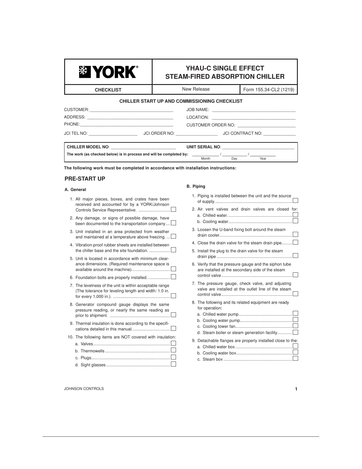
CHECKLIST
YHAU-C SINGLE EFFECT
STEAM-FIRED ABSORPTION CHILLER
New Release
Form 155.34-CL2 (1219)
CHILLER START UP AND COMMISSIONING CHECKLIST
B. Piping
1. Piping is installed between the unit and the source
of supply.
..................................................................
2. Air vent valves and drain valves are closed for:
a. Chilled water. .......................................................
b. Cooling water .......................................................
3. Loosen the U-band fixing bolt around the steam
drain cooler...............................................................
4. Close the drain valve for the steam drain pipe. ........
5. Install the plug to the drain valve for the steam
drain pipe
.................................................................
6. Verify that the pressure gauge and the siphon tube
are installed at the secondary side of the steam
control valve
.............................................................
7. The pressure gauge, check valve, and adjusting
valve are installed at the outlet line of the steam
control valve
.............................................................
8. The following and its related equipment are ready
for operation:
a. Chilled water pump ..............................................
b. Cooling water pump .............................................
c. Cooling tower fan .................................................
d. Steam boiler or steam generation facility.............
9. Detachable flanges are properly installed close to the:
a. Chilled water box .................................................
b. Cooling water box ................................................
c. Steam box ...........................................................

 Loading...


