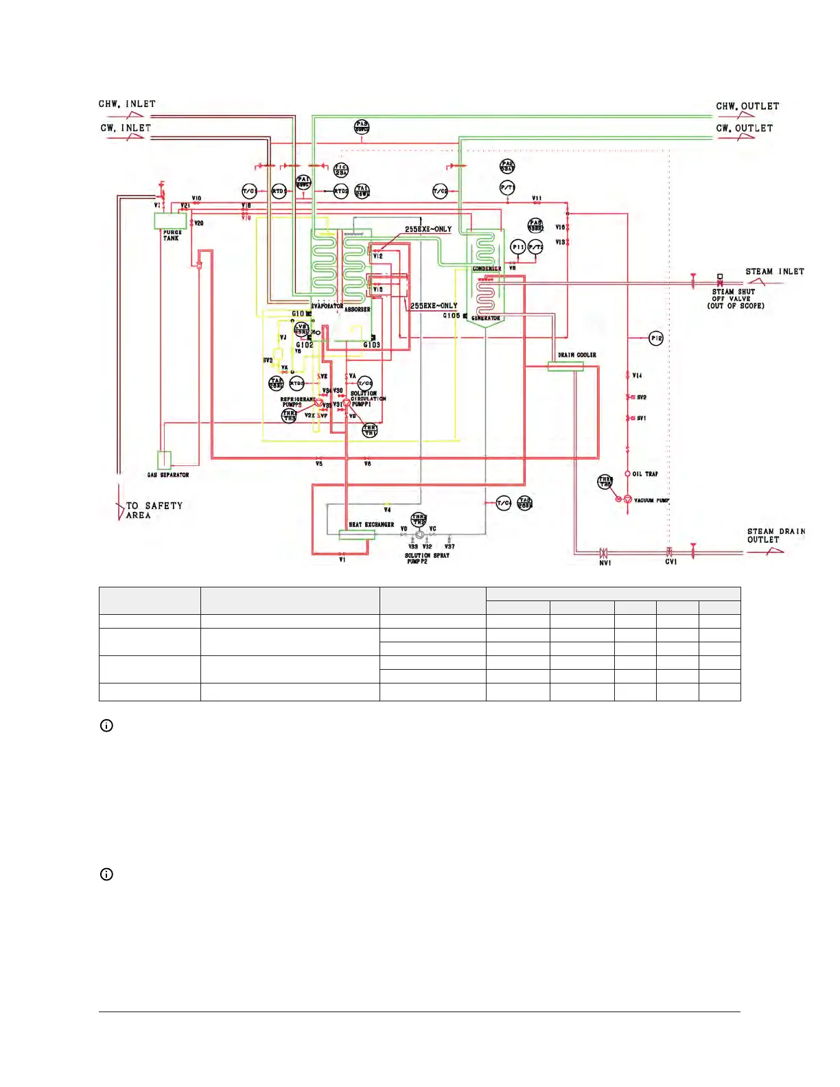
Figure 70: Process and instrumentation diagram for EXE series chiller
Valve operation/location
Purging pattern Use Operation
V10, V11 V13, V16 V14 V21 V20
A Check capacity of vacuum pump – × × O × O
Preparation × × O × O
B Direct purging from absorber
Starting purging × O O × O
Preparation × × O × O
C Manual purging from purging tank
Starting purging O × O × O
D Automatic purge of the purging tank O × O × O
Note:
1. O: Open valve.
2. X: Closed valve.
Refrigerant refining method
Note: Only use deionized water as the refrigerant in the chiller.
With an increase in the operation time of the chiller, some of the solution can mix in with the
refrigerant. Mixing the solution and the refrigerant lowers the refrigerating capacity. To prevent
this, refine the refrigerant periodically.
Refine the refrigerant according to the following procedure. The chiller must be operating to refine
refrigerant.
149YHAU-C Single Effect Steam-Fired Absorption Chiller

 Loading...


