Home
Johnson
Elliptical Trainer
JPC-5100
Page 7 (JPS-5100 Control Board Wiring Diagram)
Johnson JPC-5100 - JPS-5100 Control Board Wiring Diagram
79 pages
Manual
Save Page as PDF
To Next Page
To Next Page
To Previous Page
To Previous Page
Loading...
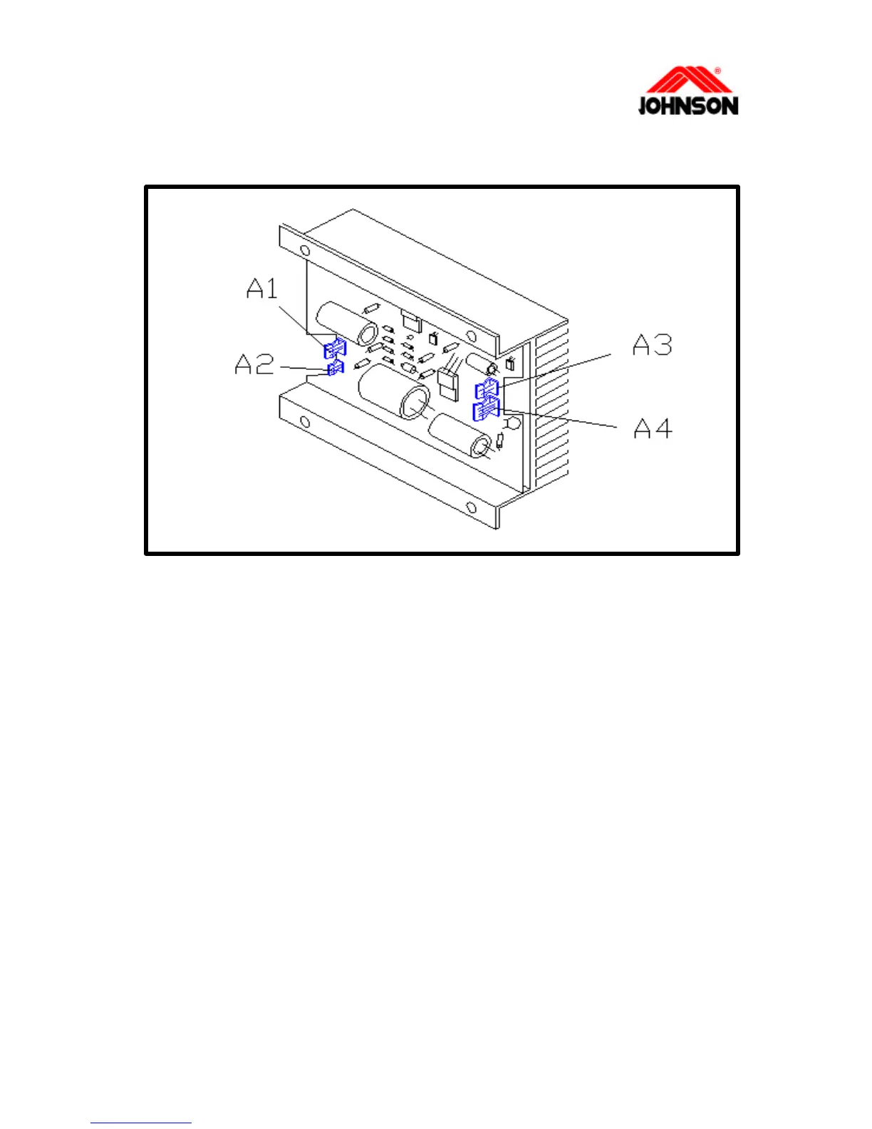
JPS-5100 CONTROL BOARD WIRING DIAGRAM
Ø
A1 :
3-pin
terminal to the generator
Ø
A2 :
2-pin
terminal to the electromagnet
Ø
A3 :
2-pin
terminal to the output of the adapter
Ø
A4 :
4-pin
terminal to the console
1-2
Revision:
1.0 Date: 2001/06/01
6
8
Table of Contents
Main Page
Default Chapter
2
Table of Contents
2
Section 1: Wiring Diagram
5
Control Board Wiring Diagram (Jps-5100)
6
Console Backside (Ear Clip Sensor)
9
Console Backside (Hand Pulse)
10
Wiring Diagram (Jps-5100)
11
Jpc/B/S/E-5100
16
No Display on the Console or the Display Is DIM
16
No RPM Is Displayed During the Exercise (JPC/B/S)
17
Resistance(Jpc/B/S)
19
Feel Slipping While Pedaling
21
Knocking or Creaking Noise
22
(Ear Clip Sensor)
23
(Chest Belt Type)
24
Console Diagnostics Mode
26
Jar-5100
28
No Display Is on the Console While any Function Key Is Pressed
28
Console will Not Function Properly
30
Jar-6000
32
No Display on the Console
32
SPM" Value Won't Increase While Running the Rower
33
No Pulse Display on the Console
34
Console
36
Console Cable
37
Control Board
37
Tools Required
38
Generator or Electromagnet Brake Set
39
Jpc/B-5100
40
Crank
40
Pedal
41
Poly-V Belt 400/380J6
42
Poly-V Belt 500/440J8
43
Axle
50
Front Pulley
50
Poly-V Belt 430J8
50
Sensor
53
Foot Pad
54
Jpe-5100
57
Crank
57
Pedal
58
Poly-V Belt 430J12
60
Pulley Axle
61
Axle
62
Roller
63
Sensor
64
Jar-5100
65
Console
65
Sensor
67
Seat
68
Drive Belt 3V-530
69
Nylon Rope
70
Tension Spring Set
71
Cleaning the Grooves
73
RE-LUBRICATING the CHAIN & GEAR (for JPS)
74
Cleaning the Rail and
75
Section 5: Service Form
76
Field Failure Report
77
Warranty Claim Form
79
Related product manuals
Johnson JPB-5100
79 pages
Johnson JPE-5100
79 pages
Johnson JAR-6100
79 pages
Johnson HORIZON FITNESS 7.0AE
28 pages
Johnson E7000
12 pages
Johnson E8000
15 pages