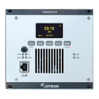
3.1.2 Scroll/Select switch and Navigation buttons A, B and C
The Scroll/Select switch together with the navigation buttons, A, B and C, are used to
navigate through the menus. The Scroll/Select switch has three actions: It can be turned
clockwise, anti-clockwise, or momentarily pressed.
In general the use of the navigation buttons are:
A has two functions: Select Channel or One step back
B has two functions: Squelch on/off or Enter/Confirm a selected submenu
C has two functions: Enter Main menu or Power on/off
SW Scroll/Select right: Increase a value (up)
SW Scroll/Select left: Decrease a value (down)
SW Scroll/Select press: Enter/Confirm
The user interface will indicate which navigation button to use.
3.1.3 ON/OFF button
Navigation button C.
To switch the transceiver ON, press and hold button for 1 second.
To switch the transceiver OFF, press button once to enter the Main menu. Then press and
hold the button for 5 seconds.
3.1.4 Front Mic/Headset connector
The front Mic/Headset connector is used for multiple purposes. First it is used to connect a
microphone and/or a headset to the front module of the transceiver for local operation. The
headset output contains the sidetone generated from the output of the transmitter together
with the received audio when the transmitter is not keyed.
In addition the Mic/Headset connector has a RS232 serial line that can be used to control
radio parameters from an external unit, or to upload new firmware into the radio unit for
future upgrades. A service dongle can be inserted to access the service menu.
Microphone Connector Front
Impedance 600 Ω. Sensitivity 3mV.
Impedance 8 – 32 Ω >100mW
Grounding this pin will key the transmitter
+3,3 VDC Power to microphone (270 Ω in serial)
Table 3.1.4-1, Front Mic/Headset connector, pin out
84417_O&I_TR-810_G Functional description
Page 3-2