Connected to + DC voltage
Ignition + DC voltage sense*
Table 3.2.2-1, DC connector, pin out *See chapter 3.2.2 for details
3.2.3 I/O connector (RJ45)
The transceiver unit I/O connector is used for multiple purposes described in the table.
To tape recorder etc. 600Ω unbalanced
Grounding this pin will force the transmitter to
1W power (Gas alarm)
Communication between B-872 & TR-810
Used to mute external equipment. Triggered by
squelch
+12 VDC to external equipment (100mA)
Table 3.2.3-1, I/O connector, pin out
3.2.4 MIC II connector (RJ45)
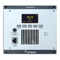
The microphone can be connected to this connector if it is convenient to have the microphone
connected at the rear side of the transceiver unit.
See chapter 4.7 and 5.5 for selecting an external microphone.
Impedance 600 Ω. Sensitivity 3mV.
Impedance 8 – 32 Ω >100mW
Grounding this pin will key the transmitter
+5 VDC Power to microphone (270 Ω in serial)
Table 3.2.4-1, MIC II connector, pin out
84417_O&I_TR-810_G Functional description
Page 3-4