PY500AC SLIDING GATE OPERATOR
8
Fig.9
Fig.9
Fig.9
Fig.9 infrared
infrared
infrared
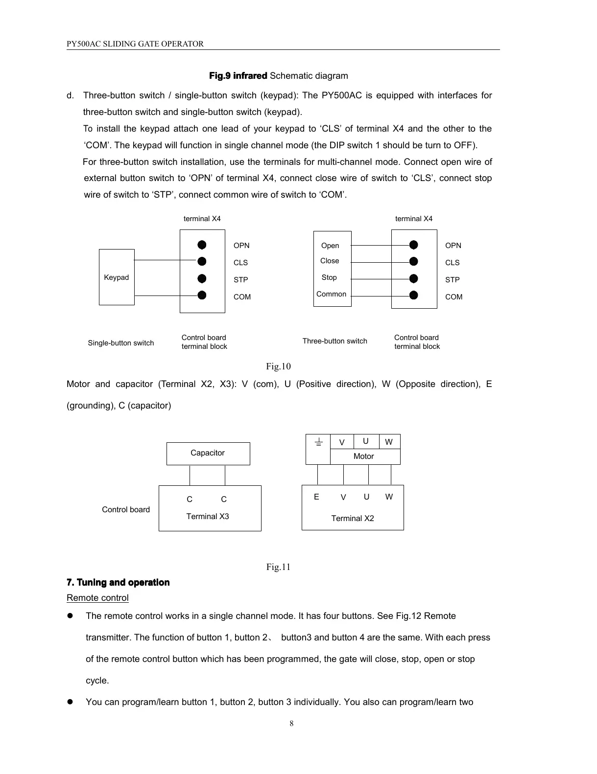
infrared Schematic diagram
d. Three-button switch / single-button switch (keypad ): The PY500AC is equipped with interfaces for
three-button switch and single-button switch (keypad).
To
install the keypad attach one lead of your keypad to ‘ CLS
’
of terminal X4 and the other to the
‘ COM ’ . The keypad will function in single channel mode (the DIP switch 1 should be turn to OFF).
For three-button switch installation, use the terminals for multi-channel mode. Connect open wire of
external button switch to ‘ OPN
’
of terminal X4, connect close wire of switch to ‘ CLS ’ , connect stop
wire of switch to ‘ STP ’ , connect common wire of switch to ‘ COM ’ .
Common
Stop
Close
Open
Three-button switch
COMCOM
Control board
terminal block
Control board
terminal block
Single-button switch
Keypad
OPN
CLS
STP
OPN
CLS
STP
terminal X4 terminal X4
Fig.10
Motor and capacitor ( Terminal X2, X3): V (com), U ( Positive direction ), W (O pposite d irection ), E
(grounding), C (capacitor)
Control board
CC
Capacitor
Terminal X3
W
U
V
Motor
W
V
U
E
Terminal X2
Fig.11
7.
7.
7.
7. Tuning
Tuning
Tuning
Tuning and
and
and
and operation
operation
operation
operation
Remote control
� The remote control works in a single channel mode. It has four buttons. See Fig.12 Remote
transmitter . The function of button 1, button 2 、 button3 and button 4 are the same. With each press
of the remote control button which has been programmed, the gate will close, stop, open or stop
cycle.
� You can program/learn button 1, button 2, button 3 individually. You also can program/learn two