FAA Approved Installation Manual for the Report No 908
EDM-900 and EDM-930 Page 13 of 55 Rev I
Primary Engine Data Management System Date 1-18-2013
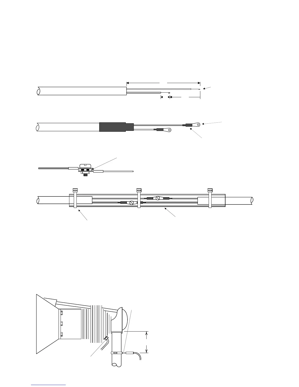
The Temperature probe must be wired with the correct polarity. The temperature probe connects to its temperature
indicator with yellow jacket Teflon Chromel Alumel wire supplied. Strip the wires as shown below—observing color-
coding.
1/4" 1 1/2"
Fold back wire
double before
crimping terminals
2 1/4"
Thermocouple wire harness
red
yellow
Terminate each wire with a crimp-on ring terminal, provided. The ring terminals may be crimped with an AMP part
number 48518 crimp tool is recommended however, a “service-type” tool may also be used. Verify the quality of
each crimp with a sharp tug on the wire. The terminal should be impossible to pull off when crimped correctly.
shrink tubing
Place a ¼ x 4-inch sleeve over each pair of wires in the wiring. Connect the wire ring lug to the probe ring lug using
the supplied number 4 screws and nuts, placing the star washer between the ring lugs, not against the nut.
Important: place star waster between two ring
terminals and tighten nut and bolt as
necessary
to instrument
to probe
Slide the sleeve over the joint and secure with three tie-wraps.
1/4 x 4" sleeve
tie-wrap 3 places
The most common installation problems are related to poor quality terminations.
9. Wiring Markings
The EDM-900/930 is supplied with special Teflon insulated Chromel Alumel factory assembled wiring harness
configured for the correct number of cylinders. The wire harness is marked E1= EGT-1, C1= CHT-1, etc.
NOTE: Unlike most other EGT & CHT installations the probe wire length is not critical and should be
trimmed to any length as required for a clean installation. Do not extend the thermocouple wire with
copper wire.
10. Exhaust Gas Temperature Probe (EGT)
Installation
Use the J2 connector harness 700700 or 700702
labeled E1 through E4 or E6. Remove the existing
EGT gauge and Probe. Replace with JPI probe M-
111 in all exhaust stacks.
The Model M-111 Probe will fit any engines where
the existing holes in the exhaust stack are 1/8" to
1/4" in diameter. If no hole exists, it will require the
drilling of a 1/8" diameter hole and ream to fit. It is
important that each probe be mounted the same
2" to 4"
EGT probe
Drill no. 40
pilot hole,
then no. 30
hole.
CHT probe
exhaust stack