FAA Approved Installation Manual for the Report No 908
EDM-900 and EDM-930 Page 14 of 55 Rev I
Primary Engine Data Management System Date 1-18-2013
distance from its exhaust stack flange. A nominal distance of 2 to 4 inches from the exhaust flange is
recommended. If the recommended distance is impractical because of obstructions, slip joints or bends in the
exhaust system then position the probes a uniform distance from the flange as space permits. Do not mount
probes in slip joints. Be certain to locate all holes BEFORE drilling to ensure that nothing interferes with the
probe, clamp, screw or wire. Careful matching of probe position will provide best temperature readings.
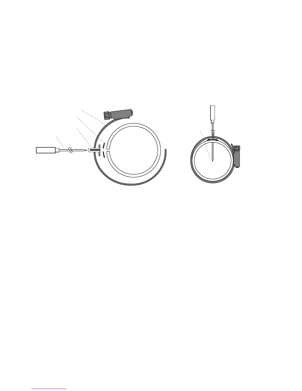
Insert the probe in the exhaust or previously drilled hole so that the tip of the probe is in the center of the exhaust
stream. Tighten the stainless steel clamp to a torque of 45 in/Lbs. Cut off the excess strap close to the screw.
Position probe
in approximate
center of
exhaust
Probe
Clamp
Thimble
note orientation of
slot
Seal Washer
11. RADIAL Engine EGT
Radial engine exhaust, require a larger EGT clamp (supplied) to fit the 2.5 inch exhaust pipe. The EGT probe is installed in the
same fashion as a Lycoming or Continental engine and should be placed between the exhaust pipe flange and the accumulator
at a distance of 2 to 3 inches from the engine exhaust flange. Refer to the engine manufactures recommended location. Do not
route the EGT/CHT harness in with the ignition harness. Do not extend the yellow thermocouple leads with copper wire.
12. Turbine Inlet Temperature (TIT) Probe Installation (optional)
Use the J1 connector harness 790200 and insert the yellow wire into the connector pin 16 and the red wire into pin
17. The standard TIT probe PN M111-T with a #48 clamp is placed in the exhaust stack accumulator to a maximum
depth of 1/2 inch and approximately 4 inches from the turbine inlet if possible, on the waste-gate side of the turbine.
13. TIT for second Turbine Inlet Temperature
Use the J1 connector harness 790200 and insert the yellow wire into the connector pin 18 and the red wire into pin
19. The standard JPI TIT probe P/N M-111-T with a special clamp is placed in the exhaust stack accumulator to a
maximum depth of 1/2 inch and approximately four inches from the Turbine inlet if possible, on the waste gate side
of the turbine.
14. Using the Factory original TIT Probe
The factory installed TIT probe (K-calibration) is compatible with the JPI EDM-960 System. Connect the JPI wire
marked TIT. Replacement probes should be purchased per part number from the aircraft manufacturer.
The EDM-960 permits you to remove the factory installed TIT indicator and leave the TIT probe installed. Connect
the JPI wire marked TIT directly to the probe noting color polarity. The TIT probe should now have only the JPI
leads attached to it. No calibration of the EDM-960 is necessary