YDFLP-E-20/30-M7 User Manual
File Number: J-SI-0036
3.3.1.1 DB25 Sequence
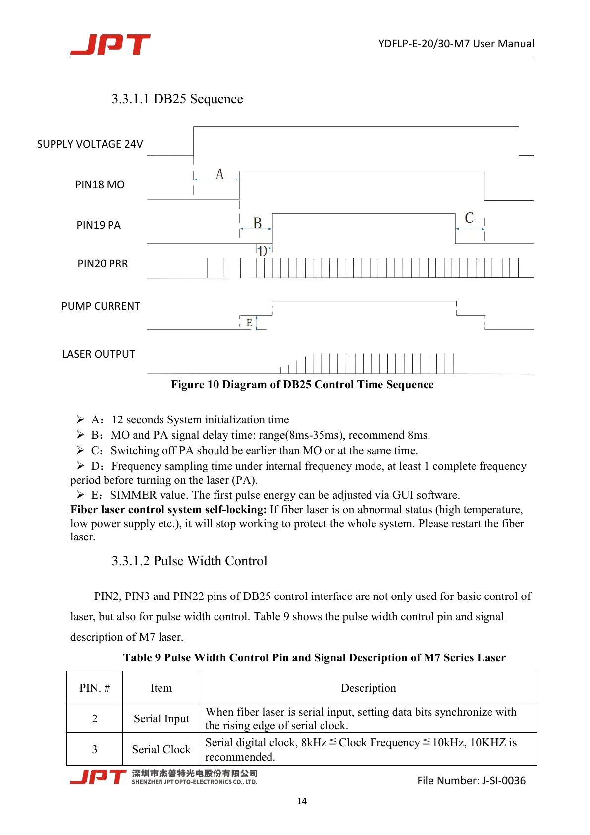
Figure 10 Diagram of DB25 Control Time Sequence
A
:
12 seconds System initialization time
B:MO and PA signal delay time: range(8ms-35ms), recommend 8ms.
C:Switching off PA should be earlier than MO or at the same time.
D
:
Frequency sampling time under internal frequency mode, at least 1 complete frequency
period before turning on the laser (PA).
E:SIMMER value. The first pulse energy can be adjusted via GUI software.
Fiber laser control system self-locking: If fiber laser is on abnormal status (high temperature,
low power supply etc.), it will stop working to protect the whole system. Please restart the fiber
laser.
3.3.1.2 Pulse Width Control
PIN2, PIN3 and PIN22 pins of DB25 control interface are not only used for basic control of
laser, but also for pulse width control. Table 9 shows the pulse width control pin and signal
description of M7 laser.
Table 9 Pulse Width Control Pin and Signal Description of M7 Series Laser
When fiber laser is serial input, setting data bits synchronize with
the rising edge of serial clock.
Serial digital clock, 8kHz≦Clock Frequency≦10kHz, 10KHZ is
recommended.
 Loading...