EasyManuals Logo

JPT YDFLP-E-60-M7-M-R User Manual

Default Icon
27 pages
To Next Page IconTo Next Page
To Previous Page IconTo Previous Page
Page #15 background imageLoading...
Page #15 background image
YDFLP-E-60-M7-M-R User Manual
11 File Number: S-PI-0035
2.3.1 DB25 Control & Sequence
2.3.1.1 Output Power Control
PIN1~8 controls the output laser power by TTL signal. The encoding can be set within the
range of 0~255 which is corresponding to the 0~100% output power. The actual output laser
power may not be a linear relationship with these settings. And the actual output power also
related to the frequency (see Figure 4). Please refer to the example in table 9 current setting:
Table 9 Current Setting (example)
Setting 1
Setting 2
Setting 3
Setting 4
PIN 1
0
0
0
0
PIN 2
0
0
0
0
PIN 3
0
0
0
0
PIN 4
0
0
0
0
PIN 5
0
0
0
1
PIN 6
0
0
1
1
PIN 7
0
1
1
1
PIN 8
1
1
1
1
Current
~50 %
~75 %
~87.5 %
~93.75%
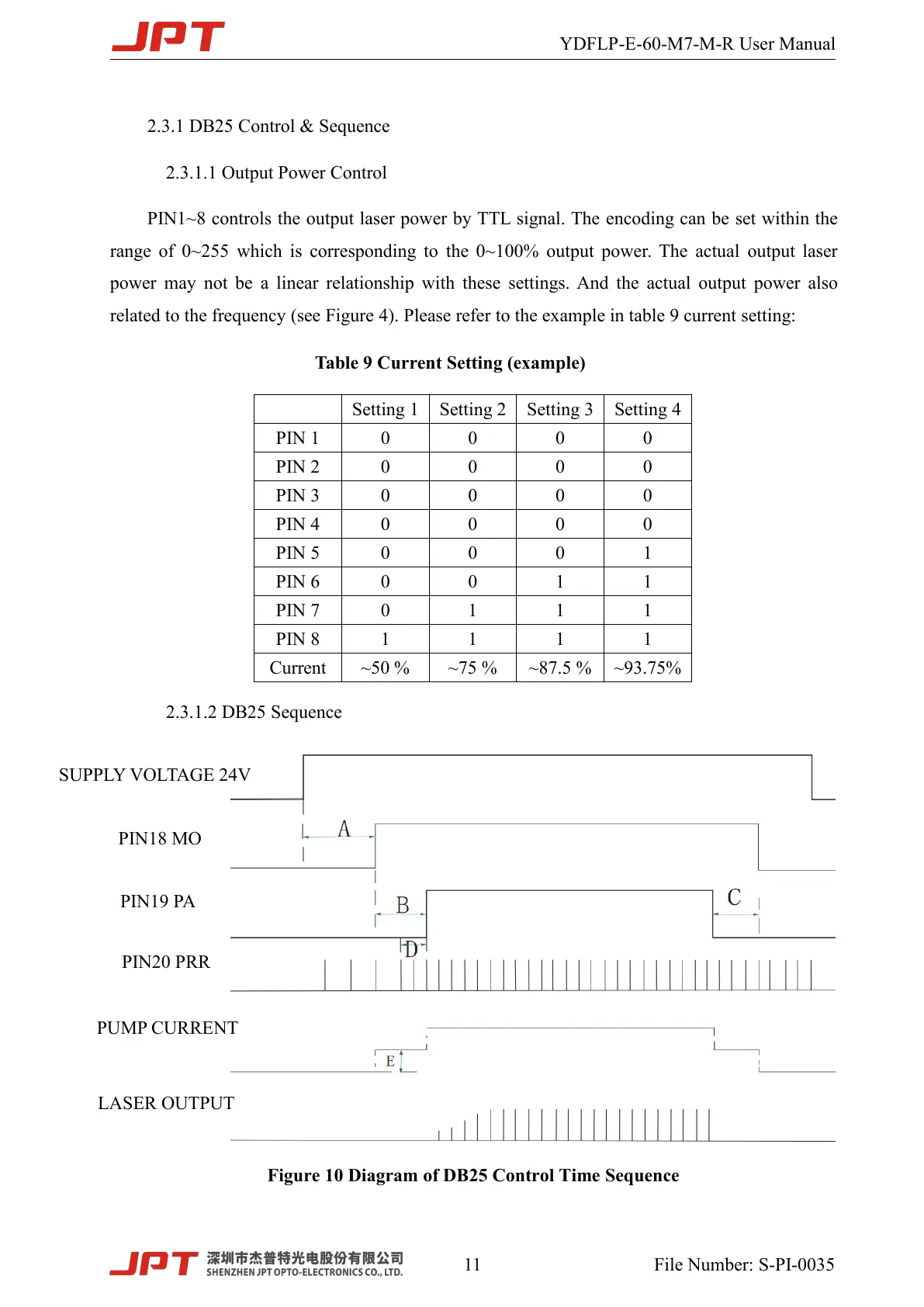
2.3.1.2 DB25 Sequence
Figure 10 Diagram of DB25 Control Time Sequence
SUPPLY VOLTAGE 24V
PIN18 MO
PIN19 PA
PIN20 PRR
PUMP CURRENT
LASER OUTPUT

Questions and Answers:

Question and Answer IconNeed help?

Do you have a question about the JPT YDFLP-E-60-M7-M-R and is the answer not in the manual?

JPT YDFLP-E-60-M7-M-R Specifications

General IconGeneral
BrandJPT
ModelYDFLP-E-60-M7-M-R
CategoryMeasuring Instruments
LanguageEnglish

Related product manuals