The elevon wing type is also commonly referred to as a delta
wing aircraft. This style of aircraft also employs two wing servos.
However, in essence there is not an elevator present. Instead, ele-
vator stick input causes the two wing servos to function in con-
junction with one another to create an up/down movement of the
aircraft. In other words, the wing itself functions as if it were the
elevator. Also, when an aileron control is given, the two wing ser-
vos move in opposition to one another to function as ailerons.
Elevon Operation
1. One servo must be used for each elevon, i.e., a separate servo
for each wing half.
2. Connect the left elevon servo to the aileron (AILE) of your JR
receiver. Plug the right elevon servo into the elevator port
(ELEV) of your receiver.
3. Check to make sure the servos move in the proper directions.
When an input is given from the elevator stick, they should
move in unison to achieve the proper up/down elevator com-
mand. If your servos do not move in the proper manner (direc-
tion) as described above, use the servo reversing function,
Code 11, to reverse the travel direction of the servo(s) that are
moving improperly.
Note: Each servo’s travel direction is adjusted individually.
Refer to Section 8.1 of this manual for more information regard-
ing servo travel direction.
4. Once the servos have achieved their proper travel direction,
adjust their travel volume, dual rates, sub-trim and aileron dif-
ferential.
Note:
Adjust the neutral point of your elevon servos individually.
To do so, use Code 15, Sub-Trim, as described in Section 8.5 of this
manual.
Note: The applicable channel’s left or right, up or down, travel
adjustments can be made individually in Code 12, travel adjust-
ment. Please refer to Section 8.2 of this manual for more infor-
mation regarding the travel adjustment.
5. Relative to the note above, each servo’s travel volume is auto-
matically reduced to 75% of the operating range. This is to
ensure that the servo does not operate beyond its capabilities.
Failure to observe caution when adjusting the value for the
elevon servos can result in damaged servos or worse!
Note: Fine adjustments of the elevons should be made in the
Dual Rates function, Code 13. Refer to Section 8.3 of this manual
for further information on the Dual Rate function.
6. To adjust the wing differential and switch positions, refer to the
wing differential feature section on the previous page.
Note: The V-tail mixing and dual tail selection is automatically
inhibited in the elevon wing type selection.
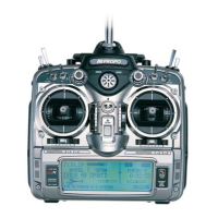
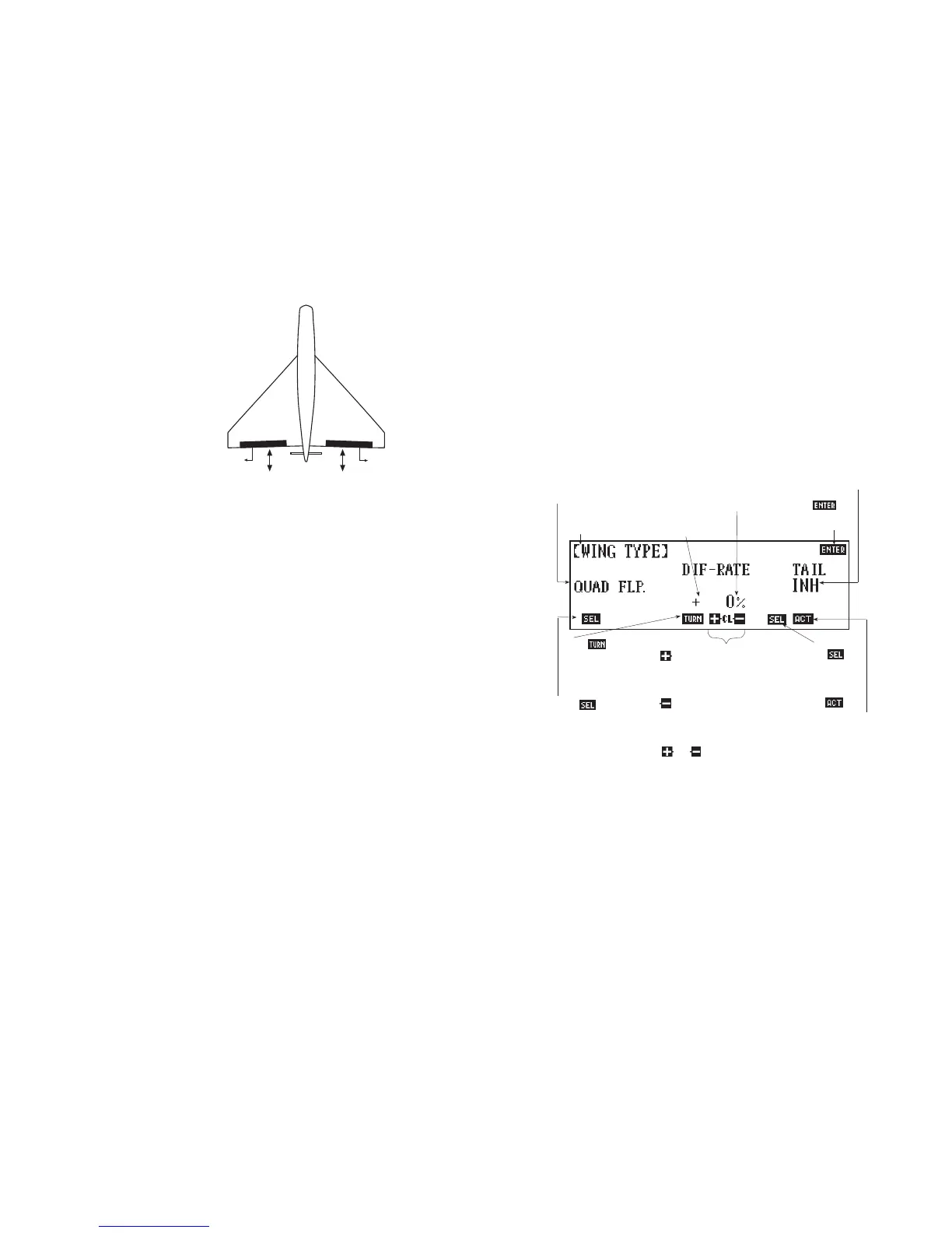
Quad Flaps
Touch the SEL key one time from the elevon wing type to select
the quad flap style wing. If you want to access quad flaps from
the normal wing type selection, touch the SEL key three times.
This style of wing employs four wing servos. The two inboard
servos function mainly as flap controls, while the two outboard
wing servos function mainly as ailerons.
Quad Flap Operation
1. One servo must be used for each control surface. Therefore,
you must employ four wing servos for this wing type selection.
2. Connect the left aileron (outboard) servo to the gear (retract)
port of your receiver. Plug the left flap (inboard) servo into the
auxiliary 1 (AUX 1) port of your receiver. Connect the right
flap (inboard) servo to the auxiliary 2 (AUX 2) port of your
receiver. Plug the right aileron servo into the aileron (AILE)
port of your receiver.
3. Check to ensure that the aileron and flap servos are moving in
their proper directions.
If your servos are not moving in the proper manner (direction) as
dictated by the gimbal stick, lever, or potentiometer control
inputs, use the Servo Reversing function, Code 11, to reverse the
travel direction of the servo(s) that are moving improperly.
10X MANUAL Airplane
31