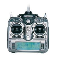
At the beginning of each code function, note that there is a brief
explanation of the code and its function.
CODE # DISPLAY PROGRAM DESCRIPTION
11 REV. SW Servo reversing—all channels
12 TRAVEL End point travel adjustments—all channels
13 DR + EXP Dual rates and exponential rate
adjustments elevator/aileron/rudder. Can
be adjusted independently for each direction
14 TRAC R Trace rate affects the total travel of both
servos when the master channel is aileron,
elevator or rudder
15 SUB TRIM Electronic means of adjusting trim of all
channels
17 FUNC S. Function select allows the controls for channels
5, 6, 7, 8, 9, 10 to be activated or inhibited,
the flight modes to be selected and flap trim,
flight mode trim and dual elevator trim to be
selected
18 THR.CURVE Two multi point throttle curves can be pro-
grammed with up to 8 stored points. Each
throttle curve can be selected via your
choice of 8 switches or flight modes
22 WING T Wing type allows the selection on normal,
flaperons, elevons, quad flaps, V-tail and
dual elevators as well as aileron differentials
(2 available).
24 SPEED Speed allows the independent selection of
servo speed on each of the 10 channels in
each of the 5 available flight modes.
28 RESET Erases the programming in the selected model
only and resets parameters to factory
defaults
31 S. ROLL Snap roll direction and values can be set and
assigned to any of 5 flight modes
44 GYRO Up to 3 Gyro gain values can be individually
adjusted and selected by the AUX 2 switch
or in any of the 5 available flight modes.
Stick priority mixing can be easily set up
using the center and end values in the
screen. The capability for using 2 gyros with
independent adjustments is available in this
function (Note: A remotely adjustable
gyro must be used)
51-55 PGM-MIX Programmable mixing selection and
adjustment are selected in any of the 5
available flight modes or a selected switch.
CODE # DISPLAY PROGRAM DESCRIPTION
56-58 MULTI-POINT Up to an 8-point programmable mix curve can
PGM-MIX be programmed and selected in any of the 5
available flight modes or a selected switch
62 A-R MIX Aileron to rudder mixing
63 E-F MIX Elevator to flap mixing
64 R-AE MIX Rudder to aileron and rudder
to elevator mix
66 FLAP S. Flap system offers 3 position flaps with
elevator compensation at each position. Flap
positions are selectable in 5 available flight
modes or on flap switch. An auto land function
is available that will automatically retract the
flaps if the throttle is advanced above a prepro-
grammed position
75 SERVO M Servo monitor gives visual indication of all
servo positions. Code 75 also has two servo test
modes
77 F SAFE Fail-safe memory and setting function in PCM
only
78 P LINK Pilot link allows control of the 4 primary con--
trols to be transferred to another JR radio via a
trainer cord, while master still remains in control of
secondary controls (i.e., flap, gear, mixes, etc.)
81 M NAME Model name input
83 TRIM RATE Trim authority is selectable for the 3 digital
trim and the mechanical throttle trim
84 MODEL Model select 1–10
85 MODULATION Modulation select SPCM, ZPCM, PPM
86 TRANS Model memory transfer only functional with
another 10X or with included DataSafe.
87 TIMER Count-down, count-up and integrated timer
functions
88 K LOCK Keyboard lock requires use of selected pass-
word to access programming
12
10X MANUAL Airplane
Code Functions
8

 Loading...