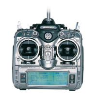
10X MANUAL Airplane
3
• Up to 5 available flight modes are selectable via a pro-
grammable switch location. Each flight mode allows the adjust-
ment and selection of nearly every parameter to alter the char-
acteristics of the airplane for differing flight regimes (e.g.,
landing, aerobatics, 3D aerobatics, takeoff, etc.). Code 17.
• Digital trims on aileron, elevator and rudder feature adjustable
trim rates, allowing the increments of each trim step to be
adjusted to the desired amount. When adjusting the digital
trims, a tone is emitted that signals each trim step. The pitch of
the tone changes based on trim position (left trim – high pitch,
right trim – low pitch ) so that the approximate trim position
can be audibly known without having to look at the transmitter.
• Digital trim positions are automatically displayed on the Info
screen. A bar graph or a digital value can be selected to display
the trim position.
• Digital trim positions are automatically stored in memory and
recalled when switching from model to model.
• A mechanical trimmer is included on throttle, offering the ease
and convenience of a visual reference during engine startup.
The throttle trim rate is adjustable in Code 83.
• Two trim options are available when flight modes are activated.
One allows each of the 5 available flight modes to have their
own separate digital trim settings that are adjustable via the
digital trim switches in each flight mode (FM trim ACT). In the
other type of available trim (FM trim INH), the digital trim set-
tings retain the same value for all flight modes and can be
adjusted while in any flight mode. Code 17
• Two programmable throttle curves are available, and up to 8
points can be stored and manipulated in each throttle curve.
Either throttle curve can be selected in any of the available
flight modes or selected by one of several switches. Code 18
• An alarm will sound if the transmitter is turned on and the flight
mode switch is not in the 0 position, warning that a possible
unsafe condition exists for startup and takeoff.
• Dual rates and expo rates are independently adjustable in each
direction. 5 rates and expo values are available through flight
modes.
• A DataSafe
TM
is included (complete systems only) that allows
the 10X to download model memory to any Windows 95
®
and
later PC for infinite model storage and security. See the
enclosed Data-Safe manual for instructions.
• A removable 1100mAh Sanyo
®
battery pack gives nearly 5
hours of continuous use. A built-in charge receptacle allows the
battery to be charged separately or in the transmitter.
• Channels 5, 6, 7, 8, 9 and 10 can be activated or inhibited,
allowing these channels to be used as slave channels during
mixing and making it so the primary control knob/lever or
switch will have no effect. Code 17.
• A dual elevator feature is pre-programmed in Code 22 and is
used on aircraft that have one (or more) servos driving each ele-
vator half. The Snap Roll function properly affects both eleva-
tors in this mode. Code 22.
• Five different rates can be programmed for the elevator, aileron
and rudder, and any combination of these rates can be selected
in any of the five available flight modes. Code 23.
• Five differing response curves (e.g., expo, VTR, expo/linear,
etc.) can be programmed for the aileron, elevator and rudder,
and any combination of these response curves can be selected
in any of the five available flight modes.
• Servo speed for all 10 channels is independently selectable in
each of the five flight modes. Code 24.
• Snap roll rate and direction can automatically be selected in
each of the five flight modes. Code 31.
• A gyro sensor adjustment provides easy gain adjustments of
any remotely adjustable gyro (JR’s NEJ900 and NEJ3000).
Three gain rates are programmable and can be automatically
selected in each of the five flight modes. In addition, stick pri-
ority mixing (especially useful in aerobatic aircraft) can be eas-
ily selected and the center point and end point gains can be
adjusted and are displayed in this screen. Code 44.
• Eight programmable mixes are available; three of which are
multi-point programmable mixes. Each mix has two available
mix values that can be selected in any of the five available flight
modes, or by a selected switch. Code 51 through 58.
• An aileron-to-rudder mix features two mix values that can be
selected in any of the five flight modes or by a selected switch.
Code 62.
• Rudder-to-aileron and rudder-to-elevator mixing features two
mix values each can be selected in any of five flight modes or
by a selected switch. Code 64.
• Three-position flaps are available in Code 66 that allow the pre-
set position for normal, mid and land flap positions, as well as
elevator compensation positions. Flap position can be selected
in each of the five flight modes or by the flap switch. Code 66.
• A servo monitor visually displays each of the ten servo posi-
tions. This handy feature is especially useful during the setup
of mixes. Code 75.
• A pilot link is provided that allows any other JR radio to be
linked via a trainer cord and allows the other transmitter to have
control of the primary controls (aileron, elevator, rudder, and
throttle) when the snap roll button is depressed, but allows all
secondary features (e.g., flaps, flight modes, gear, etc.) to be
controlled by the master transmitter.
• Touch-screen contrast can be easily adjusted by pressing the
+ or - key in the lower right-hand corner of the screen indicator
with + LCD CONT.
1.1
Transmitter
Features
1