Do you have a question about the JR XG 14 and is the answer not in the manual?
Thank you for choosing this JR product. Read this manual thoroughly for full use and safe enjoyment.
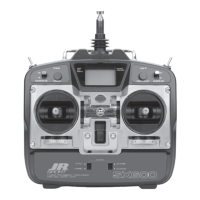
Highlights the multi-function 14-channel transmitter and its advanced capabilities for various aircraft.
Details technical specifications for the transmitter, including part number, RF, modulation, and power source.
Details technical specifications for the AC adapter, including part number, input voltage, and output voltage.
Important precautions to observe regarding possible danger from improper handling of the product.
Discusses potential interference and safety measures when using the 2.4GHz frequency band.
Explains symbols used in the manual to indicate potential dangers and safety instructions.
Provides instructions on initial setup, connection, and basic operation before starting to use the product.
Instructions on how to affix stickers for identifying switches based on model type.
Guide on adjusting the length of the control sticks for user comfort.
Information on attaching a neck strap for convenient carrying during long flights.
Procedure for inserting and removing SD cards, including compatibility and formatting requirements.
Step-by-step guide for installing and removing the rechargeable transmitter battery.
Detailed instructions on how to charge the transmitter battery safely and correctly.
Details on adjusting stick tension and the throttle stroke adjustment plate for personalized control feel.
Instructions on how to add or remove the throttle stroke adjustment plate and recalibrate.
Guidance on handling and maintaining rechargeable Ni-MH batteries for the receiver.
Explains how to connect servos and power supply to the receiver, including XBus system.
Table detailing channel assignments for Receiver connections for Helicopter, Airplane, and Glider models.
Guidance on optimal receiver antenna placement for best transmission to the transmitter.
Discusses directionality of 2.4GHz radio waves and how antenna orientation affects receiving sensitivity.
Recommendations for locating the remote antenna away from potential interference sources.
Step-by-step guide for binding the transmitter and receiver to establish communication.
Procedure to test transmitter performance by simulating long-distance range testing.
Identifies transmitter controls and their functions, varying by model type.
Details specific control names and positions for the Helicopter model type.
Details specific control names and positions for the Airplane model type.
Details specific control names and positions for the Glider model type.
Explains the function of input keys (Dial, ENTER, LIST, CLEAR, FUNCTION) for navigating and operating the transmitter.
Explains the initial information displayed on the transmitter screen, including model details and timers.
Describes the customizable 'My List' screen for quick access to frequently used functions.
Guides through the process of entering basic initial information when creating or changing a model type.
Explains the Flight Mode function for switching aircraft settings and characteristics using a switch.
Lists and explains the available flight modes for helicopters (NORMAL, STUNT, HOLD).
Lists the available flight modes for airplanes (FMOD-0 to FMOD-4).
Lists the available flight modes for gliders (SPEED, CRUISE, THERMAL, LAND, LAUNCH, etc.).
Provides examples of functions that can be modified within each flight mode, such as digital trims.
Function to switch control surface angles and curves using Dual Rate switches and exponential settings.
Allows independent adjustment of servo movement for each channel, with a range of 0-150%.
Sets limit values for servo movement to prevent excessive angle and force on linkages.
Allows fine adjustment of servo horn mounting angle for precise servo horn alignment.
Reverses the servo operating direction (pulse change direction) for each channel.
Slows down servo operation speed independently for each channel, acting as a speed limiter.
Adjusts throttle servo operation with up to 7 points, including EXPO for smooth connection.
Adjusts pitch servo operation with up to 7 points, including EXPO for smooth connection.
Sets mixing between pitch and tail servo for revolution mixing and stunt position adjustments.
Holds throttle servo at low position for autorotation landings, with options for engine cut or fixed position.
Controls gyro sensitivity using GEAR and AUX channels, supporting 3-axis gyros.
Maintains rotor rotation speed at a uniform value, setting rotation speed for stable flight.
Sets swash plate and servo mixing for coordinated helicopter control, supporting 7 swash types.
Sets throttle trim movement and includes throttle cut function for engine control.
Corrects rotor rotation speed reduction due to loading by mixing aileron, elevator, or rudder to throttle.
Sets a delay time for servo movement when switching Flight Modes to prevent jerky reactions.
Controls flaps in three stages using a switch, with delay and elevator mixing options.
Function for executing Snap Rolls, with four preset types and stick-activated options.
Corrects aircraft yaw by adjusting down-going aileron less than up-going aileron.
Allows smooth coordinated turns for scale aircraft by mixing aileron operation with rudder.
Mixes aileron operation to flaps to minimize air resistance and speed up roll rate.
Mixes elevator operation to flaps for 'air combat flaps' or snap flaps.
Mixes rudder operation to ailerons and elevators, convenient for removing biases in knife-edge flight.
Corrects individual servo characteristics to equalize travel, useful for multiple servos per control surface.
Sets maximum up and down movement of flap control surfaces independently in each Flight Mode.
Switches motor off (HOLD) or runs it smoothly using flight mode positions or delay function.
Sets full span ailerons or flaps for changing wing type, affecting descent rate and drag.
Creates air brakes using spoilers, ailerons, and flaps, also known as Butterfly or Crow mixing.
Allows setting of Flaperon mixing, mixing ailerons to flaps or flaps to ailerons/elevators.
Applies mixing to main wing camber based on elevator operation for wing root flaps and tip flaperons.
Emulates rudder operation using spoilers for aircraft with dual spoilers, acting as drag rudder.
Provides six programmable mixing systems for creating custom mixes, either normal or curve mixing.
Lists and confirms mixing conditions and basic settings, helping to discover unintentional setting mistakes.
Simulates servo operation to confirm output signals, useful for discovering mixing and switch setting mistakes.
Allows starting new model setup or switching between existing models, with up to 30 models storable.
Enables copying and erasing of model data between transmitter memory, SD card, or other JR transmitters.
Allows selection of model type (Helicopter, Airplane, Glider) and automatically starts setup wizard when creating a new model.
Allows inputting and modification of each model name, with a maximum of 8 characters.
Enables changing names for Flight Modes, with options for long (6 characters) and short (4 characters) names.
Allows changing settings related to Trims, including resolution, type, and flight mode specific adjustments.
Allows switching (ON/OFF) of virtual switches using stick operation for various functions.
Allows adjustment of mixing values or gyro sensitivity using a chosen trim lever for fine-tuning.
Sounds an alert when the Throttle Stick reaches a certain position for confirming hover or zero pitch.
Triggers an alert if throttle stick or flight mode switches are set to dangerous positions when the transmitter is switched on.
Allows basic adjustment of transmitter settings like LCD display mode, sound mode, and stick calibration.
Allows dual control flight instruction by connecting two transmitters via a Trainer cable.
Allows binding (pairing) with receiver and reducing transmitter power for range checks.
Confirms telemetry sensor data like receiver voltage, altitude, and RPM, with alarms for monitoring.
Holds all servos in their current positions, typically during radio adjustments.
Sets various flight modes, defines switch functions, and makes channel output assignments.
Sets wing type, including dual ailerons, dual flaps, dual elevators, dual rudders, and V-tail wings.
Sets predefined servo positions for loss of RF signal to prevent aircraft damage.
Reverses throttle or spoiler stick direction without changing output signal value.
Changes the stick mode between Mode 1, Mode 2, Mode 3, and Mode 4 for personalized control.
Utilizes X-Bus serial data system for communication with X-Bus products like servos.
Provides a data sheet summarizing settings and parameters for Helicopter models.
Provides a data sheet summarizing settings and parameters for Airplane (Acro) models.
Provides a data sheet summarizing settings and parameters for Glider models.
Details error messages displayed due to transmitter software issues and provides troubleshooting responses.
Information on warranty, repair services, and important cautions regarding product use and copyright.
| Channels | 14 |
|---|---|
| Model | XG 14 |
| Brand | JR |
| Modulation | DMSS |
| RF Power | 100 mW |
| Display | LCD |
| Telemetry | Yes |
| Model Memory | 30 |