85
Speed / Launch Switch (SPEED/LAUNCH)
By setting up both a SPEED(Speed Switch)and LAUNCH(Launch Switch)it is possible to set ight Modes.
① SPEED (Speed Switch) By setting a Speed switch, it is possible to use this ight mode.
፧
Speed Mode (SPEED)
፧
Cruise Mode (CRUISE)
፧
Thermal Mode (THERMAL)
LAUNCH (Launch Switch) By setting the Launch switch, it is possible to use the following ight modes.
፧
Landing Mode (LAND) Note: Landing Mode cannot be used when 2position switch has been selected.
፧
Launch (LAUNCH)
፧
Distance Mode (DISTANCE) Note: Only when Customized ight mode switch being used
፧
Zoom Mode (ZOOM) Note: Only when Customized ight mode switch being used
፧
Free Mode(FREE) Note: Only when Customized ight mode switch being used
※ Launch Switch Reverse (LAUNCH REV)
It is possible to switch the Launch Switch position on the Flight
Mode switch.
NORM : The Upper switch position(POS 0)will be set as
LAND(Landing Mode), and the Bottom switch position
(POS 2), will be set as LAUNCH(Launch Mode).
REV. : The reverses the positions for LAUNCH and LAND – POS
0 becomes LAUNCH (Launch Mode) and POS 2 becomes
LAND (Land Mode).
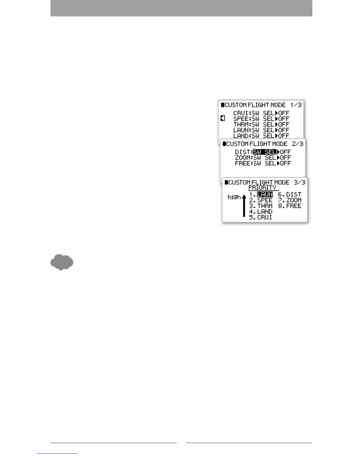
② When adding "SPEED/LAUNCH" as a custom ight mode
It is possible to set a custom switch for choosing the Flight Mode
when ‘Speed/Launch’ is selected. It is also possible to select the
priority for each ight mode. Select the switch position using the
"SW SEL" function then choose the priority for each ight mode.
Device Select (DEVICE)
Here input devices (switches, levers and trim switches) can be linked
to a particular channel. Select the device as desired.
Selection of output (OUT)
Here the Output conguration of each channel can be specied.
INH: No output.
ACT: Allow output - standard.
MOT: Use this channel for Motor control.
※ The channels which can be allocatable for Motor control are “GEAR”(Gear Channel)and “AUX3”(AUX 3 channel)
When the Motor Channel is set, “MOTOR SYSTEM” on the function List becomes activated.
Even though a channel’s OUT (Output) can be set to “INH”, it is possible to use the channel with a “PROGRAM
MIX” (on the function List) as a Master channel. It is also possible to set this under “DEVICE SELECT”
Touch Select function: When selecting a switch, by operating the switch that you wish to use, the switch will be
automatically recognised and be set to that function. It is useful when you are not sure of the switch name.
It is possible to select from the following three (3) movement options when using a trim lever as an Input
device.
2P: 2position movement
3P: 3position movement
MO: Momentary Movement
▋▋Caution▋Note
Actually operate the servos and carefully conrm the settings before ying.
Device Select Selection of outputSelection of output
Flight mode Extension Switch
Selection of Extension Switch
Device Select Selection of output
Selection of outputFlight mode Extension Switch
Device Select Selection of output
Selection of output Flight mode Extension Switch
Launch Reverse Switch

 Loading...