56
▋Program▋Mixing【PROGRAM▋MIX▋1-6】
▋▋Function▋Explanation
If a mixing function is required that is not already incorporated in the transmitter, six program
mixing systems are provided for use. These can be used to freely structure your own mixes.
For this mixing, either simple normal mixing or curve mixing that allows setting of a curve
using multiple points can be selected.
▋▋Setting▋Method
Normal mixing and Curve mixing
With Helicopter models, there is only one (1) available mixer which can be activated by switch or by ight
mode. On Airplane and Glider models, there are two (2) mixers available that can be activated by switch or by
ight mode.
፧
Selection of the Master Channel and Function of Master Include
Select the Master Channel for inputting the program mix. The channel name may be dierent depending
on the type selection (please refer to chart 1 below).
There is an option available to include or not include any trim or other mixing to the program mixing in
regards to the Master channel.
፧
Slave channel Selection
Select the Channel for outputting the mix. The channel name may be dierent from the default depending
on the type selection (please refer to chart 2 below).
There is an option available to include or not include any other mixing with the program mix in regards to
the Slave channel.
፧
Throttle stick (Coupling function) (THRO STK) Only for Airplane
It is possible to switch between two desired positions using the throttle stick. Initially this is set to INH.
Activate the function as necessary.
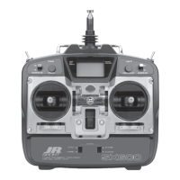
Normal Mixing
By default, this is set to “INH”. Select Normal for using this Program Mixing. To “INH” this function, move the
cursor to the Master/Slave channel selection, then press the CLR key.
፧
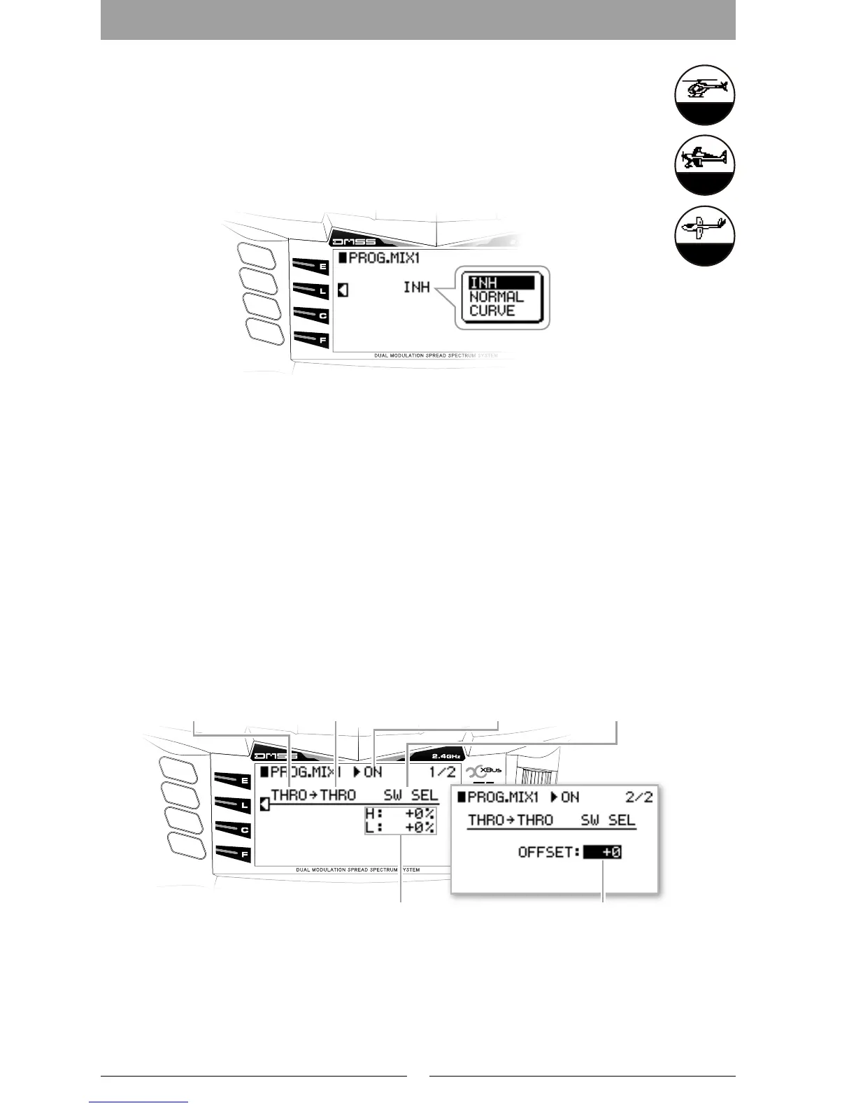
Mixing Reference Point Oset (OFFSET)
By setting an OFFSET, the mixing Reference Point can be changed to the desired Mixing point on the
Master Channel.
Helicopter
Airplane
Current positionMaster channel Slave channel
Mixing value
Master channel Slave channel
Mixing Offset on reference point
Switch Selection
In put Position and
Output Position of
Each Adjustment
Point
Point Addition and Deletion
Flight Mode
This changes the point
Connections to a Curve
Numerical Display of Stick Input Position
and Output Position
Switch Selection

 Loading...