32
▋Gyro▋Sensitivity【GYRO▋SENS】
▋▋Function▋Explanation
This function controls the gyro sensitivity using the GEAR channel, and the Auxiliary (AUX)
channel if required. It allows adjusting the gyro sensitivity from the transmitter. Further, it
supports “Dual Gain” as employed in JR’s G7000 where two channels are required. Additionally,
the use of two gyro units is also possible. In addition, it supports 3 axis gyros (such as JR
TAGS01), with separate gains for yaw, pitch and roll axis. The sensitivity switching of each gain
can be with individual switches, or combined using the Flight Mode switch.
▋▋Setting▋Method
It is necessary to allocate the Gyro Sensitivity to a channel using “DEVICE SELECT” in the System List. Set “OUT”
as “GYRO” by activating the function.
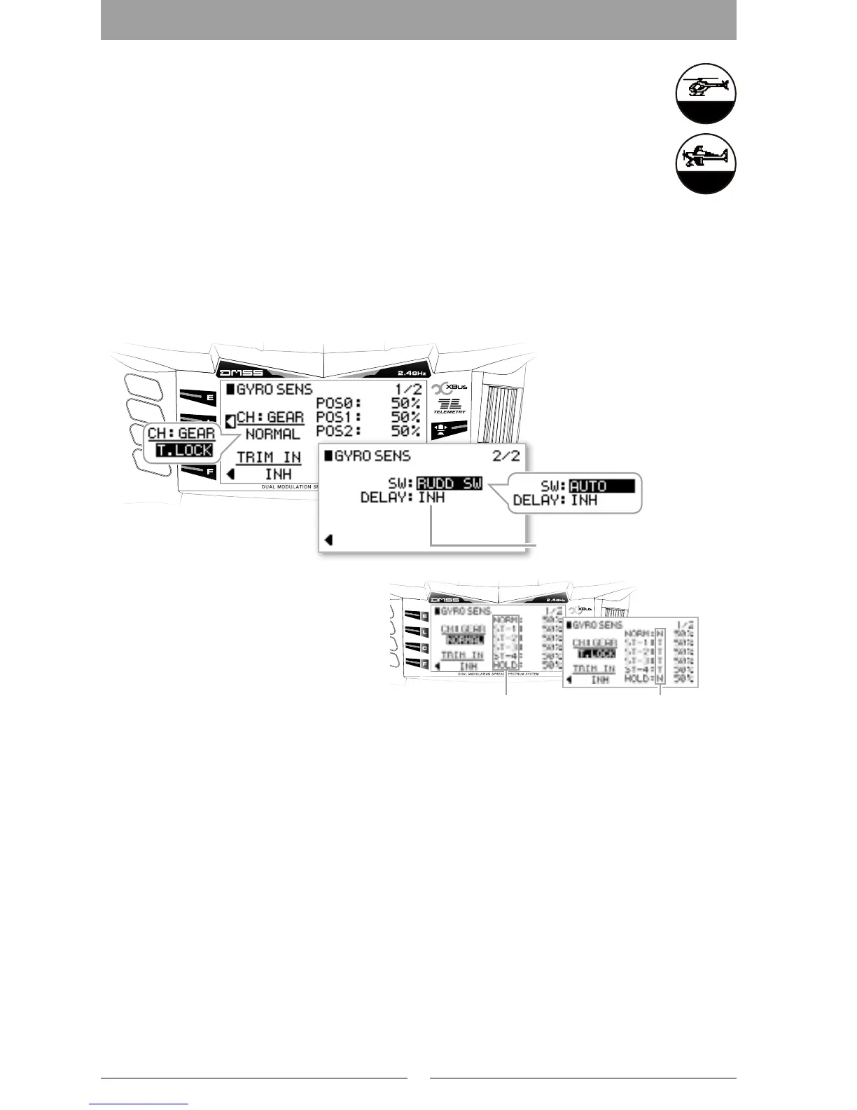
Select the switch position for changing the gyro sensitivity and move the cursor to each position to set the
sensitivity on the display. If “AUTO” is selected, the sensitivity switching setting for each flight mode will be
applied.
There are two gyro sensitivities available - “NORMAL” and Tail Lock (T.LOCK) - choose the type depending on
your application.
Gyro sensitivity Switching delay (DELAY)
To avoid excessive servo hunting when switching
the gyro sensitivity from a low sensitivity to
higher sensitivity setting, (e.g. when the main
rotor blade rpm is not stable) it is possible to set
a delay on this function.
Note: During switching, the time will be delayed
only in the high sensitivity direction.
Trim Input Function (TRIM IN)
By using the Trim Input, it is possible to change
the gyro sensitivity values using a Trim Lever.
Therefore, it is possible to easily adjust the sensitivity during ight.
When two individual channels have been selected for Gyro sensitivity, it is possible to select from the following two
modes.
፧
"TWO GYRO"
It is possible to allocate two individual gyro sensitivities, and the Gyro sensitivity switching can occur on one
shared switch.
፧
"DUAL GAIN"
In this mode, one channel is allocated for “NORMAL” and the other channel to “TAIL LOCK SENSITIVITY”.
※ For 3 Axis gyro applications (such as the JR TAGS01) three separate gain channels can be used. Each
sensitivity for yaw, pitch and roll axis can be set using individual switches, or combined onto the ight mode
switch. The gyro sensitivities can also be changed to Normal or Stunt Modes when using the JR TAGS01.
“Calibration for 3 Axis Gyros”
The JR 3 Axis Gyro system (TAGS01) as used for Flybarless R/C helicopters requires “CALIBRATION” prior
to ying. This is required to recognize the type of CCPM being employed, and learn the servo travel ranges
used. Calibration requires precise gimbal stick movement of one function at a time (Elevator or pitch stick up
& down, and Aileron stick right to left). If, for example, the aileron stick is pushed by mistake during elevator
calibration, the calibration will be incorrect. In order to avoid this problem, the calibration function allows
single channel calibration.
Display for corresponding
flight mode
Gyro Mode selection
S = STUNTT = TAIL LOCKN = NORMAL
Gyro sensitivity (T.LOCK)
Calibration function
TRIPLE AXIS MODE
Setting values and actual output values
NORMAL
-150% -100% -50% 0% 50% 100% 150%
0% 50% 100% 125%
T.LOCK
T
N
-150% -100% -50% 0% 50% 100% 150%
0% 50% 100% 150%
-150% -100% -50% 0% 50% 100% 150%
0%50%100%150%
TRIPLE AXIS
S
N
-150% -100% -50% 0% 50% 100% 150%
0% 50% 100% 150%
-150% -100% -50% 0% 50% 100% 150%
0%50%100%150%
DUAL GAIN
NORM GAIN
T.LOCK
-150% -100% -50% 0% 50% 100% 150%
0% 50% 100% 125%
0% 50% 100% 150%
-150% -100% -50% 0% 50% 100% 150%
The upper numerical values are the
setting values.

 Loading...