9
▋Receiver▋Connections
Receiver Connections to the servos and the
power supply
JR labels the channels on the receiver with
names rather than numbers. From this point
onward in the manual, the receiver channels
will be described using their names.
Since the receiver is susceptible to
vibration, shock, and water, anti-vibration
and waterproofing measures should be
implemented.
If the connectors become detached while
ying, there will be a risk of uncontrolled
operation. Please securely insert all of the
connectors as far as they will go.
In the situation where relay connectors
(extension leads) are used during
installation rubber sponge should be
wrapped round the connectors to x them.
Be absolutely sure not to leave the
connectors hanging unsupported.
XBus
The all new XBus system uses JR's own
serial bus data instead of PWM (Pulse
Wide Modulation) to communicate with
XBus products such as servos.
Control signals are sent in a serial
manner to all channels, with individual
servos recognizing their own data from
receiver.
Non XBus servos can still be used in
conjunction with a channel decoder (e.g.
XB1-CPR), or plugged directly into the
receiver (avoiding the XBus port).
Never plug any non XBus device into the
XBus system as a failure is sure to occur.
On large models, our optional XBus
power hub allows servos to receive a separate power supply.
Our new XBus receiver is also able to be plugged directly into compatible helicopter FBL units, allowing a
single connection between the receiver and FBL unit.
▋▋Connection▋list▋to▋Receiver
RX
RX
RX
RX
× Wrong Antenna Installation
The arrows show the receiving direction with
regard to the antenna.
Carbon frame
Receiving
Sensitivity
(High)
Receiving Sensitivity
(High)
Receiving Sensitivity (High)
Receiving
Sensitivity
(Low)
RX
RX
Take care not to damage
the antennas projecting
from the aircraft body.
Weak
Signal
Strong
Reception
Strong
Reception
RG Cable 150
RG831B Main Unit
Remote Antenna
Built-in Antenna
▼
Front Face
▲
Rear Face
Strong
Reception
Strong
Reception
Weak
Signal
RA01T Side View
Built-in Antenna
Circuit Board Face
Due to the 2.4GHz band which has a strong directionality in
its radio waves, the receiving sensitivity will greatly differ
depending on the direction against the antenna. Since the
antenna receives radio waves from the sides rather than
from the tip, please take adequate care of the antenna
direction when installing the antenna in the model.
The built-in antenna of the remote antenna is
installed on the surface of the circuit board.
Care will be required in the situation where the
built-in antenna has been installed beside a
shielding material, since the receiving
sensitivity will be considerably degraded.
* The remote antenna receives the data and also
feeds back to the transmitter.
The antenna part should be installed
in a perfectly straight condition.
Coaxial part of the antenna can
be bent however, do not bend it
in a right angle. This will damage
the internal antenna wires.
If each antenna is installed in parallel, the receiving
efficiency will be reduced.
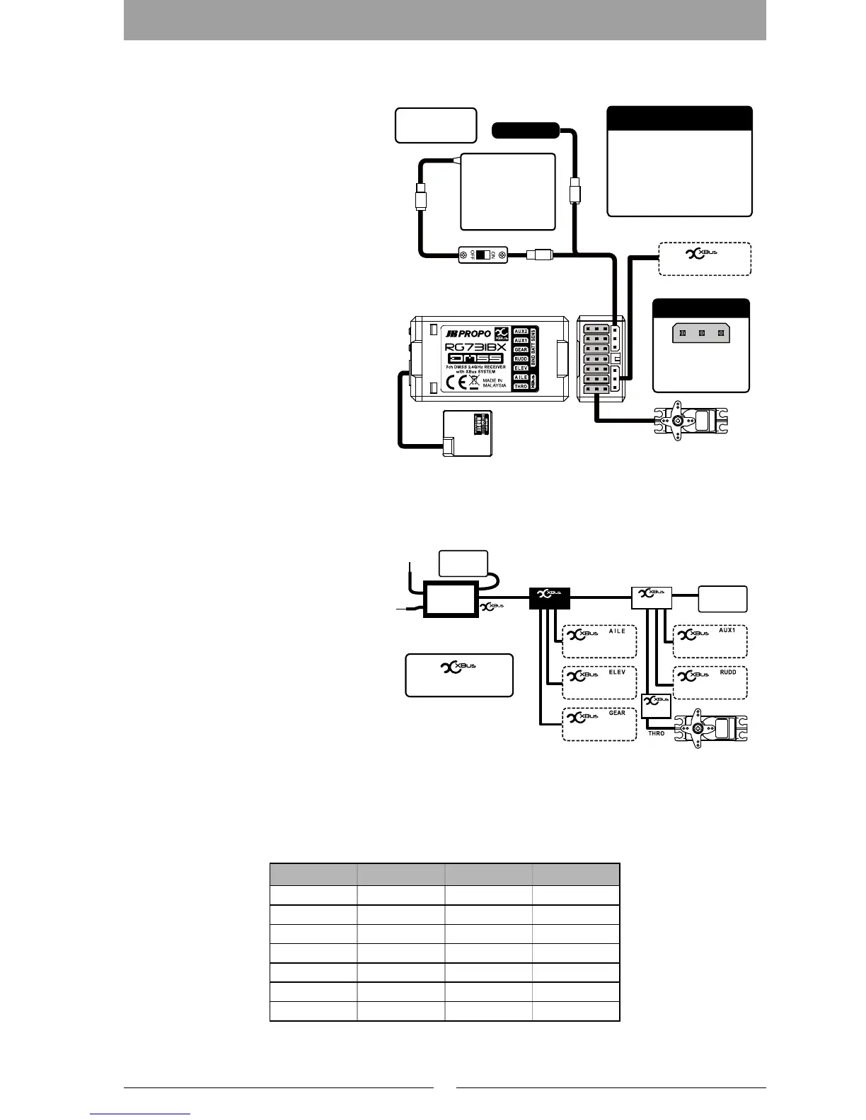
Receiver Battery
(sold separately)
SENSOR
Sensor(sold separately)
Connection
Diagram
Switch Harness
(sold separately)
When inserting the
connectors, take
note of the correct
direction.
RG731BX Receiver
Close up of the connector
Sensor Connections
When connecting sensors, use
a Y-Harness (sold separately)
connected to the [BIND/BAT-
T/SENS] terminal.
* It is not necessary to carry
out binding for the sensor.
Conventional servo
(sold separately)
X.Bus system products
Remote antenna
Y-Harness
(sold separately)
RX
wiring example
Conventional Servo
X.Bus Compatible servo
BATTRY
BATTRY
HUB
HUB
Converter
Output Port
(1ch)
(2ch)
(3ch)
(4ch)
(5ch)
(6ch)
Servos can be operated
from a separate power
supply by using the
optional 'X-Bus power hub'.
※
X.Bus Compatible servo
X.Bus Compatible servoX.Bus Compatible servo
X.Bus Compatible servo
※
Aircraft body surface made
from shielding material
RX
RX
RX
RX
× Wrong Antenna Installation
The arrows show the receiving direction with
regard to the antenna.
Carbon frame
Receiving
Sensitivity
(High)
Receiving Sensitivity
(High)
Receiving Sensitivity (High)
Receiving
Sensitivity
(Low)
RX
RX
Take care not to damage
the antennas projecting
from the aircraft body.
Weak
Signal
Strong
Reception
Strong
Reception
RG Cable 150
RG831B Main Unit
Remote Antenna
Built-in Antenna
▼
Front Face
▲
Rear Face
Strong
Reception
Strong
Reception
Weak
Signal
RA01T Side View
Built-in Antenna
Circuit Board Face
Due to the 2.4GHz band which has a strong directionality in
its radio waves, the receiving sensitivity will greatly differ
depending on the direction against the antenna. Since the
antenna receives radio waves from the sides rather than
from the tip, please take adequate care of the antenna
direction when installing the antenna in the model.
The built-in antenna of the remote antenna is
installed on the surface of the circuit board.
Care will be required in the situation where the
built-in antenna has been installed beside a
shielding material, since the receiving
sensitivity will be considerably degraded.
* The remote antenna receives the data and also
feeds back to the transmitter.
The antenna part should be installed
in a perfectly straight condition.
Coaxial part of the antenna can
be bent however, do not bend it
in a right angle. This will damage
the internal antenna wires.
If each antenna is installed in parallel, the receiving
efficiency will be reduced.
Receiver Battery
(sold separately)
SENSOR
Sensor(sold separately)
Connection
Diagram
Switch Harness
(sold separately)
When inserting the
connectors, take
note of the correct
direction.
RG731BX Receiver
Close up of the connector
Sensor Connections
When connecting sensors, use
a Y-Harness (sold separately)
connected to the [BIND/BAT-
T/SENS] terminal.
* It is not necessary to carry
out binding for the sensor.
Conventional servo
(sold separately)
X.Bus system products
Remote antenna
Y-Harness
(sold separately)
RX
wiring example
Conventional Servo
X.Bus Compatible servo
BATTRY
BATTRY
HUB
HUB
Converter
Output Port
(1ch)
(2ch)
(3ch)
(4ch)
(5ch)
(6ch)
Servos can be operated
from a separate power
supply by using the
optional 'X-Bus power hub'.
※
X.Bus Compatible servo
X.Bus Compatible servoX.Bus Compatible servo
X.Bus Compatible servo
※
Aircraft body surface made
from shielding material
Receiver Helicopter Airplane Glider
1) THRO THRO THRO LAILE
2) AILE AILE AILE RAILE
3) ELEV ELEV ELEV ELEV
4) RUDD RUDD RUDD RUDD
5) GEAR GYRO GEAR GEAR
6) AUX1 PIT. FLAP FLAP
7) AUX2 GOV AUX2 AUX2

 Loading...