29
▋Pitch▋Curve【PITCH▋CURVE】
▋▋Function▋Explanation
This function adjusts pitch operation in response to throttle stick operation. The servo position
can be set independently for a maximum of 7 point positions. In addition, an EXPO (exponential)
function is also incorporated to allow smooth throttle stick connection of each of the points.
This function is available in each Flight Mode for helicopters (maximum 6), and 2 modes for
airplanes.
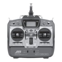
▋▋Setting▋Method
There are three initial curve points set at the slow, center, and high positions. To add a point, set the stick to
the desired position and press the “ADD” key. In the situation where a point is to be deleted, this should be
carried out using the “DEL” key. To change vales at each point, rotate the dial to move to and select the point
that you wish to change (inverse display). Then press the dial to select and change the numerical value.
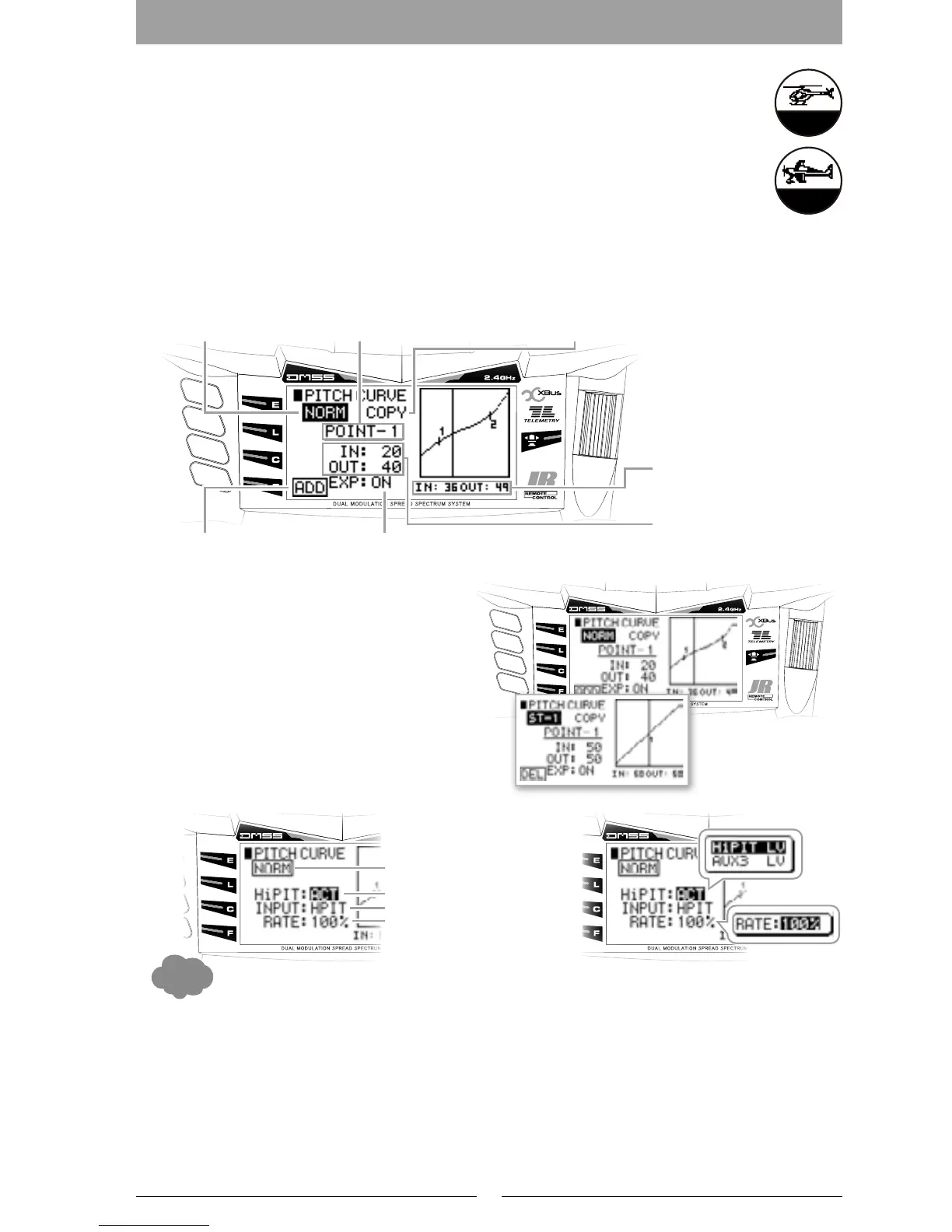
High Pitch trim (HiPIT)
High Pitch Trim Lever
Using the lever on the side of the transmitter,
pitch adjustment at the high point is possible.
This function is initially inhibited – it must
be activated to use. After activating, select
the lever either on the left or right side of the
transmitter using “INPUT”. The lever should
normally be left in the center position, and
should be used for dynamic adjustment.
The numerical value “IN” shows the position of the throttle stick and the numerical value “OUT” shows the
output value to the servo.
Adjustment is possible over an adjusting range between 0 and 100% for each of the slow to high (up and down)
directions.
Points 1, 2, and 3 will be inuenced by the Hover Pitch Trim and this will be seen on the graph. In addition, the
High Pitch Trim will inuence Point H.
▋▋Caution▋Note
After the setting, operate the servos and carefully conrm each of the Flight Mode settings before ying.
Adjusting point DisplayCurrent Flight Mode position
Point addition and deletion This changes the point connections to a Curve.
Numerical Display of the
Stick input Position and
output position
Each Adjusting point input
Position and output position
Copy function
Movement Amount
Usage Lever
High Pitch Lever usage
Current Flight Mode position
Caution:
Points 1, 2 and 3 will be
influenced in the Hover-
ing pitch trim and also
the graph.
In addition, the High
pitch trim will also be
influenced in Point H.
Normal mode
Stunt mode
Adjusting point DisplayCurrent Flight Mode position
Point addition and deletion This changes the point connections to a Curve.
Numerical Display of the
Stick input Position and
output position
Each Adjusting point input
Position and output position
Copy function

 Loading...