52
▋Brake▋system【BRAKE▋SYSTEM】
▋▋Function▋Explanation
This function creates air brakes using the spoilers, ailerons, and flaps. The function is also
known as Butterfly mixing and Crow mixing. When the spoiler stick is lowered, the flaps will lower and
the ailerons will be lifted. Looking from the front of the aircraft you will see the whole wing will no longer
generate lift, and will have a huge amount of drag. A blind band can be set to prevent mis-operation when
operating the spoiler stick. In addition, the trim correction provided by the elevators can be nely adjusted to
the corresponding air brake angle using curve points.
▋▋Setting▋Method
First set the mixing amount provided from Spoiler Stick operation to the ailerons and aps.
Then adjust the Stick position where this mixing will be started.
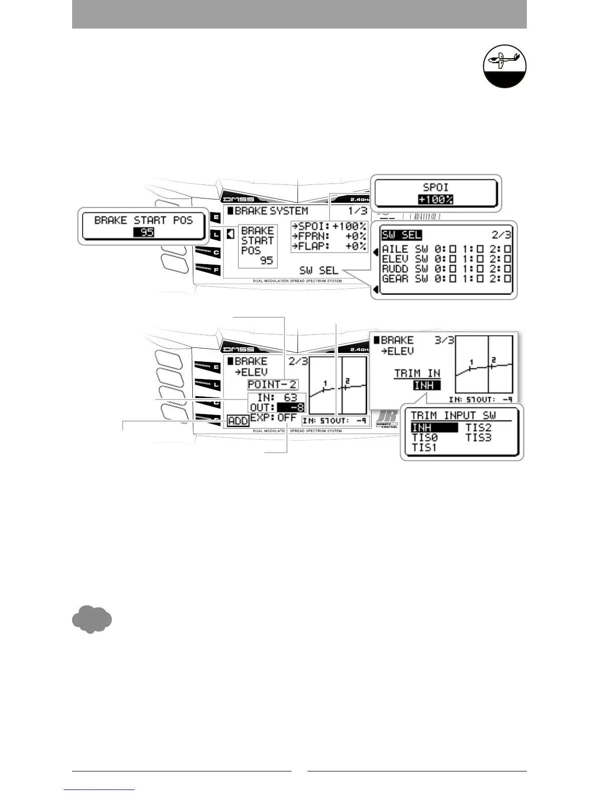
Brake Start Position (BRAKE START POS)
This adjusts the stick position where the brake operation will be started. It is possible to arrange a ‘blind band’
to prevent mis-operation when operating the spoiler stick.
Spoiler Travel Adjustment
By setting the “ → SPOI” it is possible to set the Spoiler travel in response to Spoiler Stick position. As a default,
the Spoiler is set to the AUX2 channel.
Trim Input Switch (For Elevator)
The Trim Input switch can be used to trim the elevator. Individual points can be adjusted using the Trim Input
on the multi-point curve. The point “0” is the maximum brake amount. With the Trim Input Switch it is easy to
adjust the precise settings during the ight.
In quick summary: The brake is set as spoiler by default; this is because AUX2 is set as the Input device “SPOI
STK” in Device Select. In another words, it is possible to allocate another switch or lever to control the Brake
function under the System List.
▋▋Caution▋Note
When this function is fully operated, the servos will move a considerable amount. At this time, care is required
to avoid applying an unreasonable force to each of the control surfaces. Use the Limit Adjust function to apply
limits to servo movement to avoid damaging the control surfaces or servos.
After programming these settings, operate the servos and carefully conrm each of the Flight Mode settings
before ying.
This shows the movement angle
when the spoilers are incorporated.
Adjustment Point Display
This adjusts the stick
position where the
brake operation will
be started.
In put Position and
Output Position of
Each Adjustment
Point
This changes the point Connections to a Curve
Point Addition and Deletion
Numerical Display of Stick Input Position and Output Position

 Loading...