2.Installation of Scanner Unit > 2.1 Equipment Cable
2-8
Twist each pair of the following colored wires and clamp them to the crimp pin terminal. (V5.5 is
recommended.)
• RED.T/GRN.T → + terminal
• WHT.T/ORN.T → + terminal
• PUR.T/BRN.T → - terminal
• BLU.T/GRY.T → - terminal
After that, insert each crimp pin terminal into TB840 of RADAR INTERFACE CIRCUIT CQD-2273
according to the procedures shown below. (A slotted screwdriver is required.)
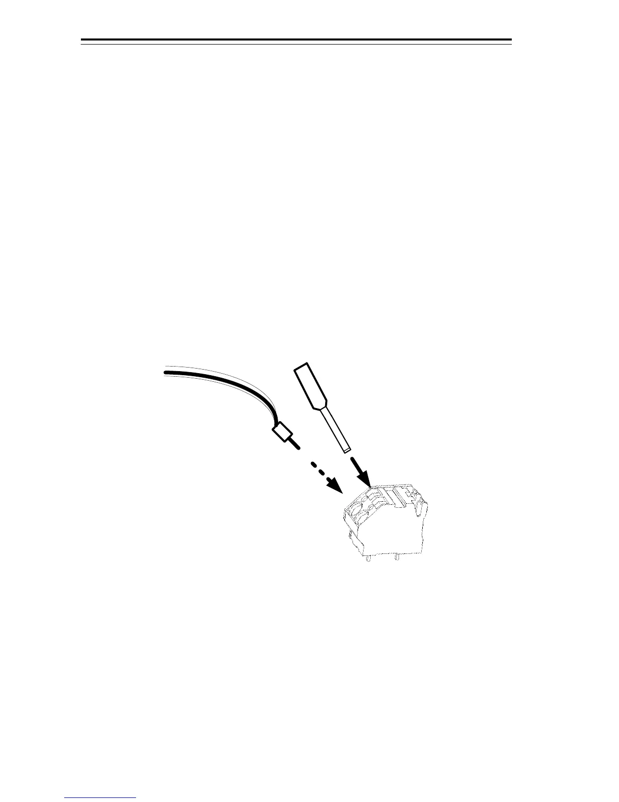
●How to insert the pin terminals into TB840:
(i) Insert your flat head screwdriver into the upper slot of TB840.
The cable slot (lower slot) will open.
(ii) Insert the crimp pin terminal into the cable slot (lower slot).
(iii) Pull out your flat head screwdriver and the pin terminal will be fixed.
TB840
a Pin terminal
a Flat head screwdriver
Twist each pair of the following colored wires and connect them to the J832 of RADAR INTERFACE
CIRCUIT CQD-2273.
• YEL.T/PNK.T → J832(DC+)
• BLK.T/SKY.T → J832(DC-)

 Loading...


