2.Installation of Scanner Unit > 2.1 Equipment Cable
2-1
2. Installation of Scanner Unit
2.1 Equipment Cable
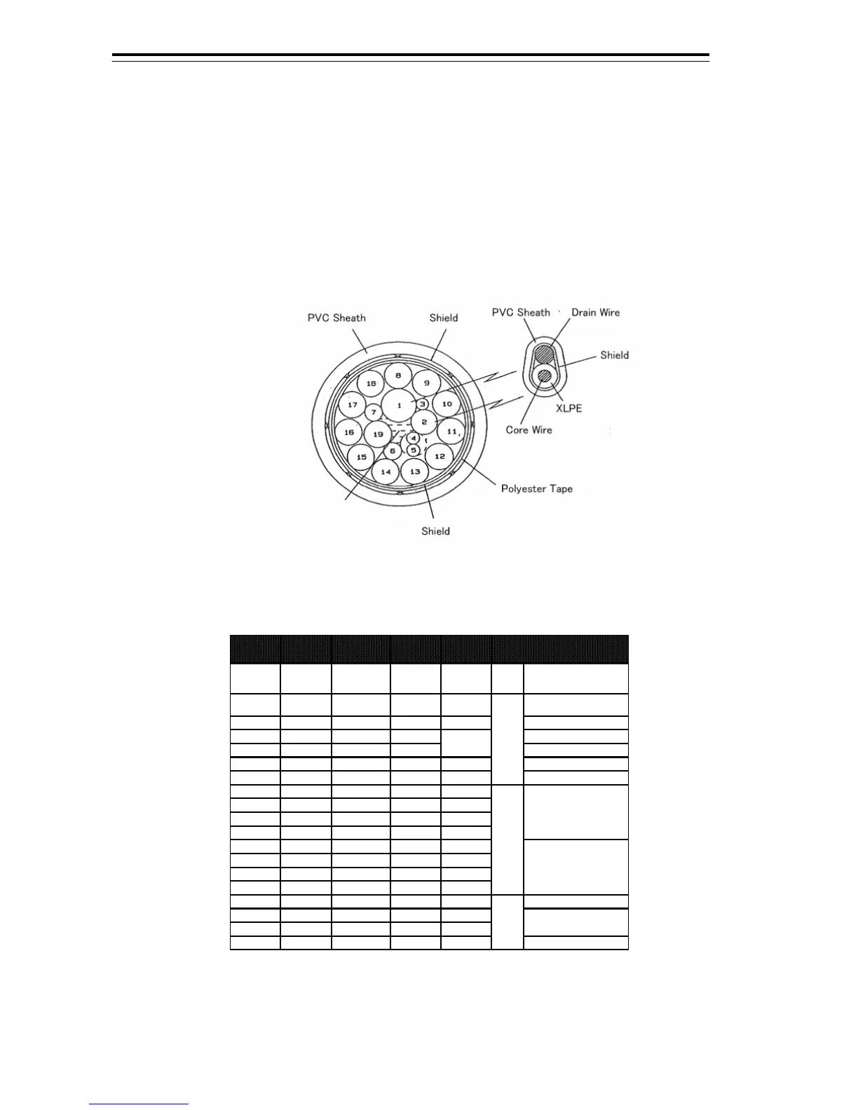
2.1.1 CFQ-6912-**
This is a 19-core shielded composite cable.
The cable length is indicated in the asterisks ** area in the model name, and the available cable lengths are 5,
10, 20, 30, 40, 50, and 65 meters.
This cable is used to connect an NKE-2103 type scanner or an NKE-2254 type scanner to the display unit.
Fig 2-1 Cross-sectional drawing of CFQ-6912
Table 2-1 CFQ-6912 wire
Core (No.) AWG No. of Wire /φ Color Remarks
1 AWG24 7/0.2T Black1 Coaxial J832
Center Conductor: 1. VD+
Outer Conductor 2. VD-
2 AWG24 7/0.2T Black2 Shield
3. TRG+
4. TRG-
3 AWG24 7/0.2T Green 7. BZ+
4 AWG24 7/0.2T Yellow 9: MTR+
5 AWG24 7/0.2T White 10: MTR-
6 AWG22 17/0.16T Black 6. BP-
7 AWG22 17/0.16T Orange 5. BP+
8 AWG16 50/0.18T Blue
9 AWG16 50/0.18T Gray
10 AWG16 50/0.18T Purple
11 AWG16 50/0.18T Brow n
12 AWG16 50/0.18T White
13 AWG16 50/0.18T Orange
14 AWG16 50/0.18T Red
15 AWG16 50/0.18T Green
16 AWG16 50/0.18T Yellow 13. DC+
17 AWG16 50/0.18T Black
18 AWG16 50/0.18T Sky
19 AWG16 50/0.18T Pink 13. DC+
CQD-2273
Radar Interface Circuit
1. +
14. DC-J832
TB840
2. -
J832
Tw isted Pair
Black
Black
maximum diameter 14.5mm
 Loading...


