EasyManuals Logo

JRC JAN-9201 Installation Manual

JRC JAN-9201
100 pages
To Next Page IconTo Next Page
To Previous Page IconTo Previous Page
Page #74 background imageLoading...
Page #74 background image
2.Installation of Scanner Unit > 2.1 Equipment Cable
2-11
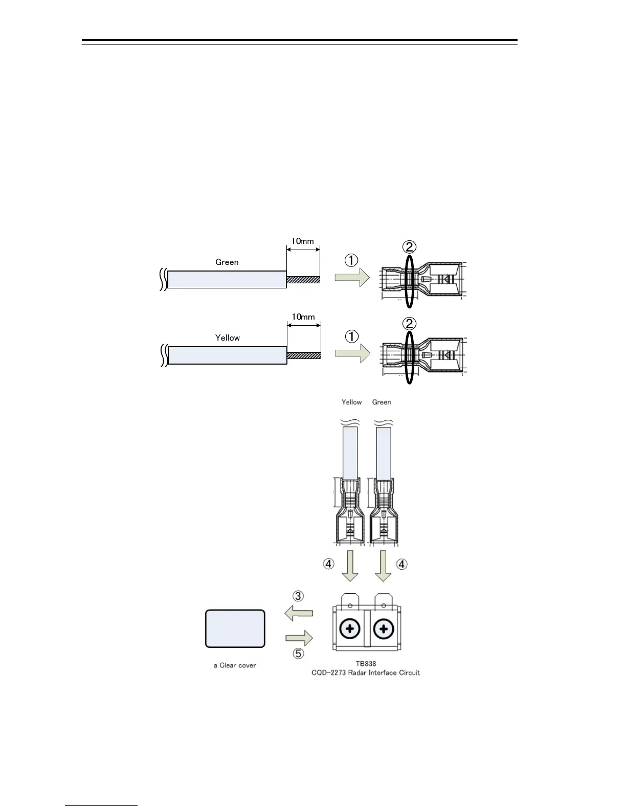
In order to connect the AC power lines that are Green and Yellow wires of 2695110056 to the
Junction Box, the Faston terminals are required.
1) Insert the Green or Yellow wire into the Faston terminal.
2) Crimp the wire.
3) Remove the clear cover of TB838 on CQD-2273 Radar Interface Circuit.
4) Connect the Green or Yellow wires with Faston terminal to TB838 surely.
5) Return the clear cover surely.

Other manuals for JRC JAN-9201

Questions and Answers:

Question and Answer IconNeed help?

Do you have a question about the JRC JAN-9201 and is the answer not in the manual?

JRC JAN-9201 Specifications

General IconGeneral
BrandJRC
ModelJAN-9201
CategoryMarine Equipment
LanguageEnglish

Related product manuals