8.4 REPLACEMENT OF MAJOR PARTS
ņ44
8
yyyy
yyyy
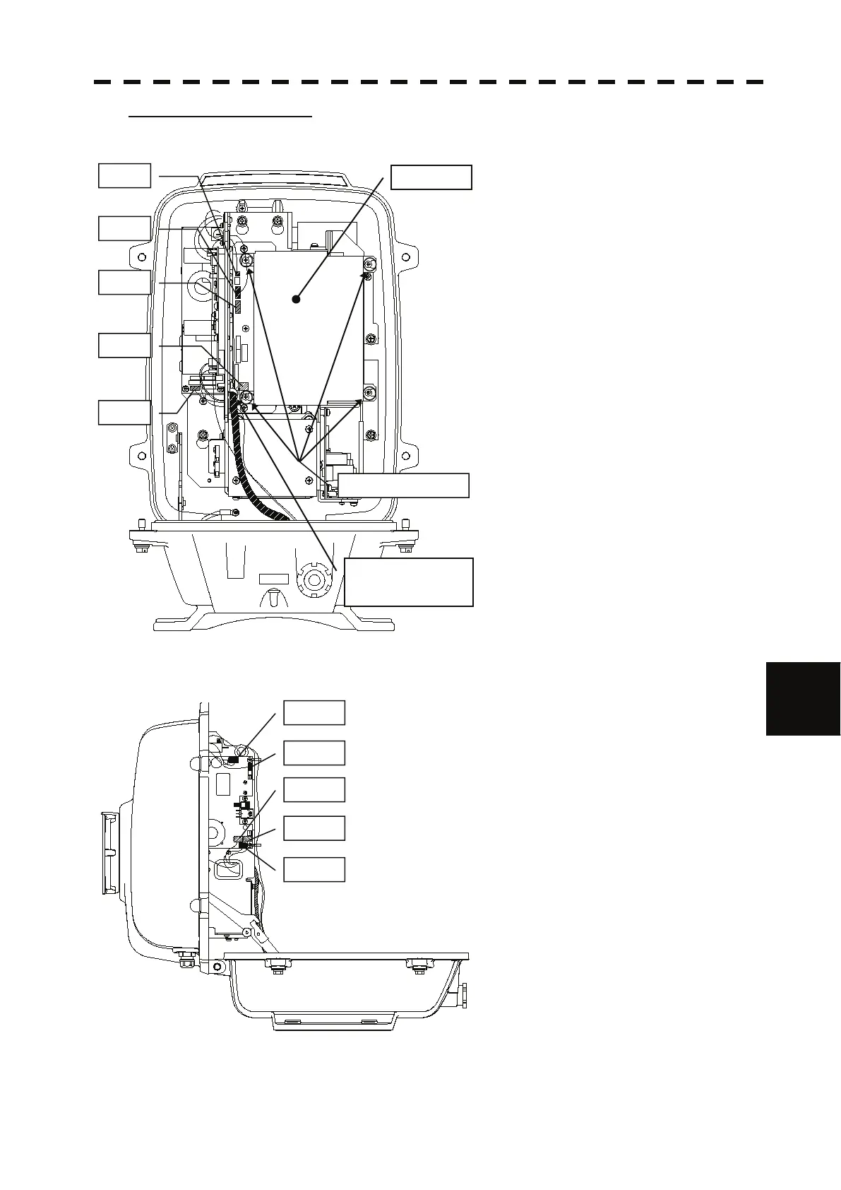
Step 3: Remove the cable.
Loosen all the screws (4 places).
Slide the cover to the left and remove it.
Remove the encoder connector (1 place).
(J209)
Remove the equipment cable connectors
(5 places).
(J1 through J5)
Remove the safety switch connectors
(2 places).
(J210 and J1504)
Remove the motor connector (2 places).
(J1502 and J125)
Remove 10 connectors in total.
* When a PM monitor (optional) is installed,
remove the connectors (2 places) and then
remove the screwed ground terminal.
Remove the screw (1 place) and remove the
cable clamp as well as the equipment cable.
J209
J210
J1
J2
J3
Screws (4 places)
Cover
Cable clamp screw
(1 place)
J1502
J125
J4
J5
J1504

 Loading...


