2.2 FUNCTIONS OF SOFTWARE BUTTONS
2ņ8
2
y y
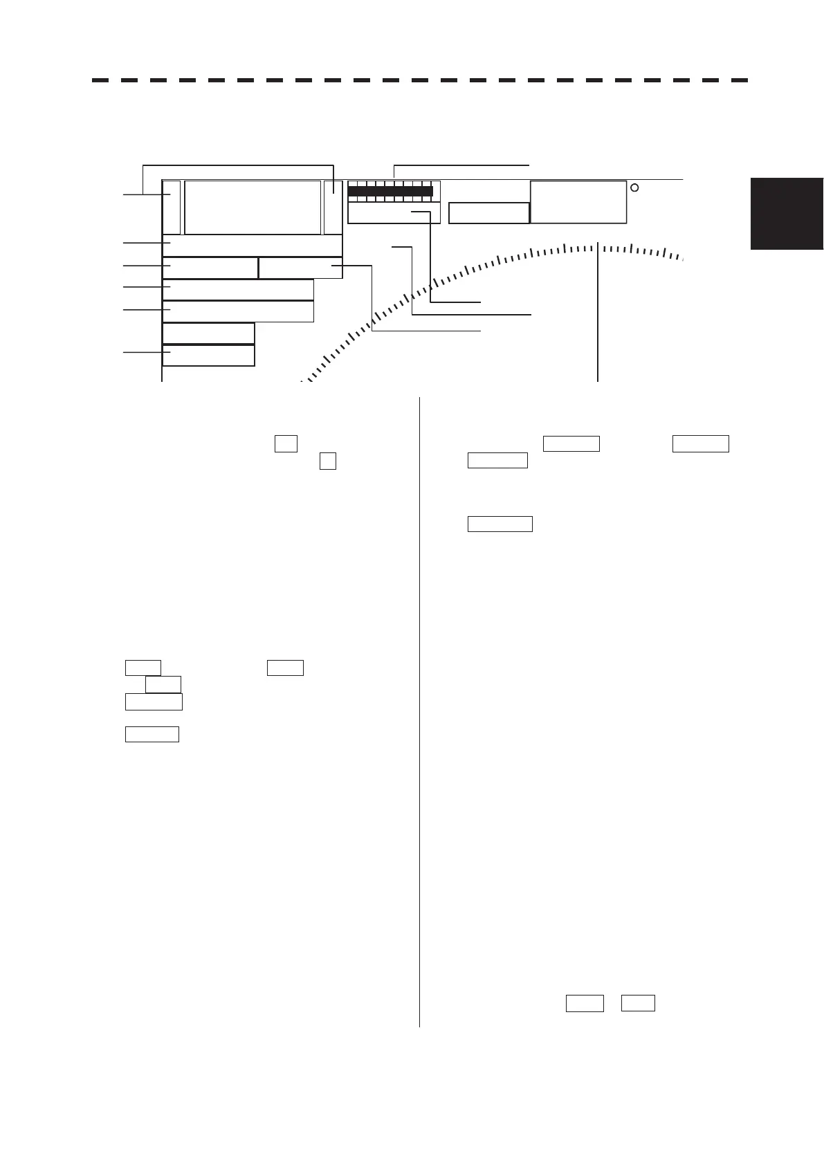
2.3.1 Software Buttons for Area 1 (Top-Left Corner of the Radar
Display)
6
+
-
Rings 1NM
RM(R) H UP
Off Center
Transmit
GND
HDG
Compass
000
01
320
330
340
350
000.0
X-BAND
Master
MP
Range scale switching
To increase the observation range scale
(maximum 96NM), click + and to reduce the
range (minimum 0.125NM), click - .
Range rings display On / Off
The display of range rings are set to On / Off
whenever this button is clicked.
When the display is set to On, the interval of the
fixed range marker is displayed.
Motion mode true / relative
switching
The screen motion mode is switched whenever
the button is clicked.
TM (true motion) RM (relative motion)
TM
RM(R) indicates that the radar trails is a
relative trail.
RM(T) indicates that the radar trails is a true
trail.
Off center switching
If this button is clicked, the cursor is moved, and
the [ENT] key is pressed, the ship's position can
be moved to the cursor position. The moving
range is within 66% of the radius.
If the button is clicked for 2 seconds, the
off-center is set to Off and the ship's position is
returned to the center of the screen.
Transmission / standby switching
At expiration of the pre-heat time after the power
is turned on, Preheat changes to Standby .
Standby : Indicates a standby state. If this
button is clicked in this state, the
equipment is set to a transmission
state.
Transmit : Indicates a transmission state. If
this button is clicked in this state,
the equipment is set to a standby
state.
Interswitch connection change
This button is displayed when the interswitch is
connected. This button indicates the connection
status of the scanner unit that is connected to the
indicator.
If the button is clicked in the transmission standby
state, the menu for changing the connection state
between the scanner unit and the indicator is
displayed. The connection state of the scanner
unit and indicator cannot be changed unless the
master indicator is in a standby state.
o Refer to the Interswitch (Optional)
Instruction Manual that is attached for the
setting method. This button is not displayed
if the interswitch is not connected.
Transmission pulse length
switching
The transmission pulse length is switched
whenever this button is clicked. Three types of
pulses are available, short pulse (SP), middle
pulse (MP), and long pulse (LP). The pulse length
and repetition frequency vary even for the same
short pulse, according to the range that is used and
it is displayed as SP1 , SP2 .

 Loading...


