8.4 REPLACEMENT OF MAJOR PARTS
ņ52
8
yyyy
yyyy
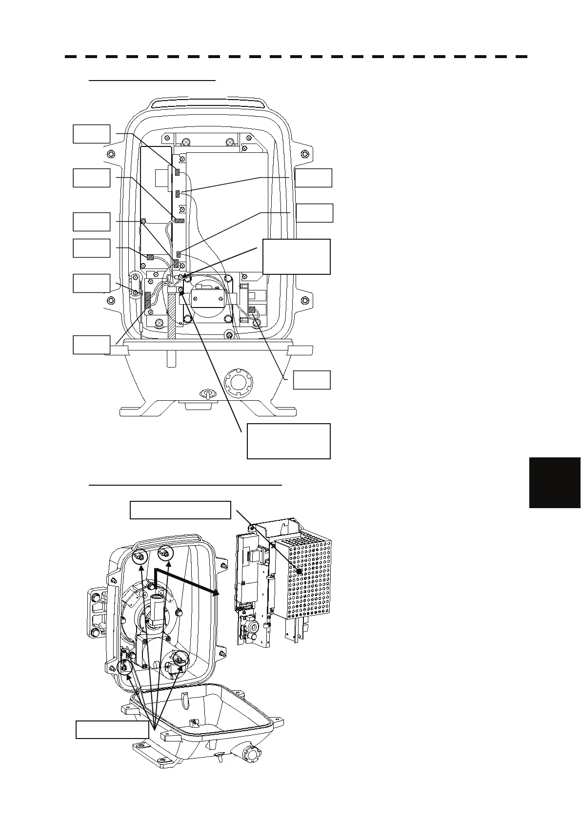
Step 3: Remove the cable.
Remove the equipment cable connectors (5
places).
(J1 through J5)
Remove the safety switch connectors (2
places).
(J15 and J16)
Remove the motor connectors (2 places).
(J11 and J13)
Remove 9 connectors in total.
Remove the screw (1 place) and remove the
ground terminal.
Remove the screw (1 place) and remove the
cable clamp as well as the equipment cable.
Step 4: remove the transmitter-receiver.
Loosen all the screws (4 places).
Slide upward and remove the
transmitter-receiver.
J2
J1
J3
J4
Cable clamp
screw (1 place)
Ground
terminal
screw (1 place)
J5
J11
J13
J16
J15
Screws (4 places)
Transmitter-receiver

 Loading...


