3-36
3
1) Output for sub display unit
The slave output includes the following signals:
- Video signal (50 ohm termination)
- Trigger signal (180 ohm termination)
- Rotation signal (open collector output)
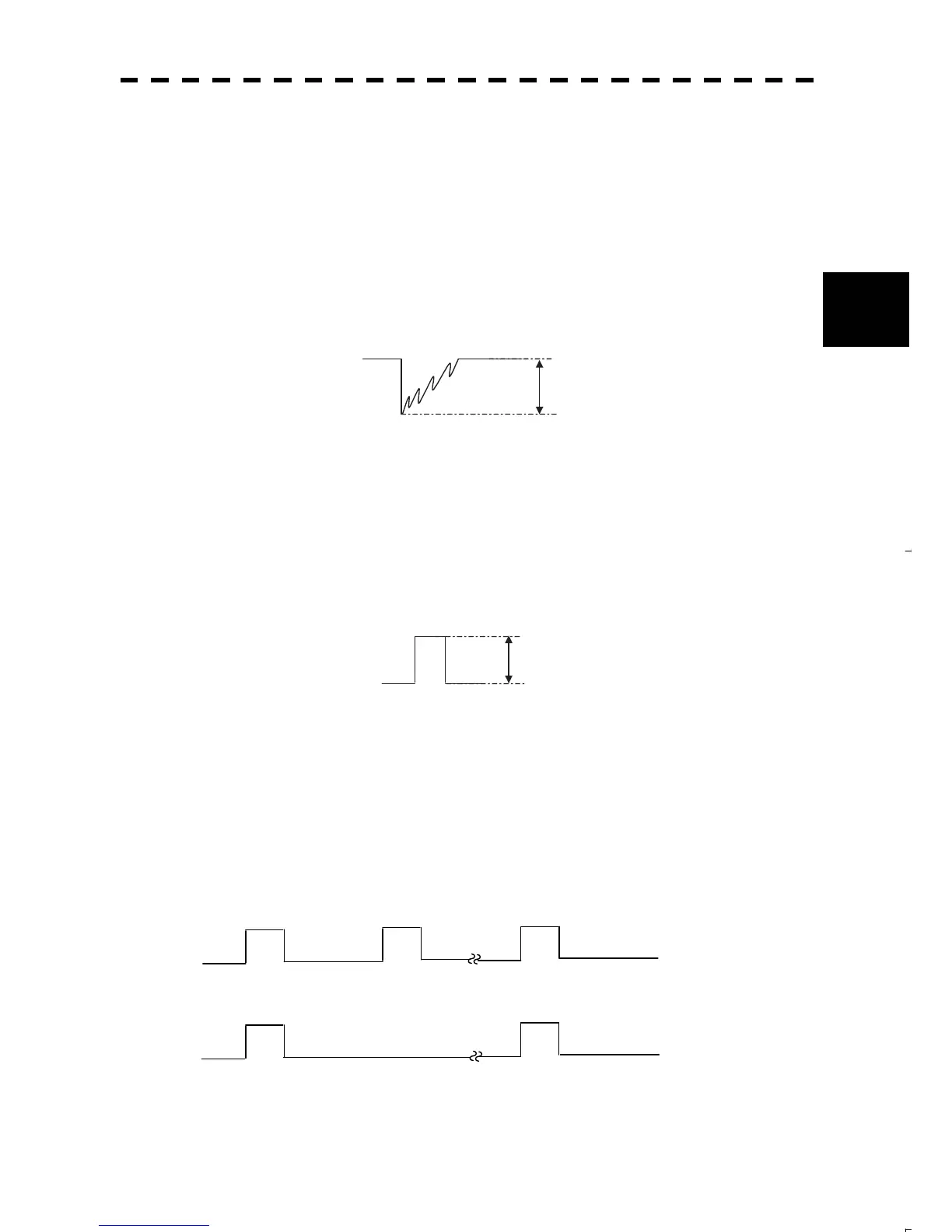
- Video signal
Connect the video signal line to the following terminals located on the terminal board:
J9-1 EVDO
J9-2 EVDOE (return)
The video signal is a negative signal and the wave form is as follows:
8
- Trigger signal
Connect the trigger signal line to the following terminals located on the terminal board:
J9-4 ETRGO (TTL output)
J9-7 ETRGOE (return)
The trigger signal is a positive signal and it takes approximately 6P seconds from the startup to the video
signal.
8
x Rotation signal
Connect the rotation signal line to the following terminals located on the terminal board:
J9-5 EBPO
J9-7 ETRGOE (return)
Connect the rotation reference signal line to the following terminals located on the terminal board:
J9-5 EBZO
J9-7 ETRGOE (return)
Pull up both lines to 5 V at 1 kilo-ohm before using them.
BP
2048 pulses per
c
 Loading...


