8.4 REPLACEMENT OF MAJOR PARTS
ņ50
8
yyyy
yyyy
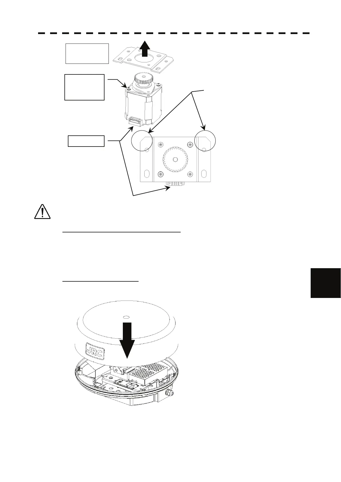
Pay attention to the orientation of the motor.
For installation, pay attention to the orientation of the mounting plate and the motor (connector positions).
The motor connector is positioned in reverse to the chamfer of the mounting plate.
Step 6: Install the motor into the scanner.
Be sure to tighten all the upset head bolts with specified torque.
Connect the motor cable to the connector on the motor.
After connection, check the cables not to interfere the antenna rotation.
Apply grease to the gear after installing the motor.
Step 7: Attach the radome.
Before attaching the radome, check that the packing has no abnormality, such as deformation or
cracks. Also, remove foreign material and dust if attached.
If any hexagonal bolt is not tightened enough or is loosened, the waterproof performance
may be deteriorated. Be sure to tighten all bolts with specified torque (10.5kgf·cm).
This completes the motor replacement procedure.
Do not
remove the
damper.
Connector
Mounting
Plate
Upper view
Pay attention to the orientation of the
mounting plate and the motor
(connector positions).
 Loading...


