JMA-9100/7100 Installation Manual > 2.INSTALLATION OF SCANNER UNIT > 2.4 PRECAUTIONS
2-29
2
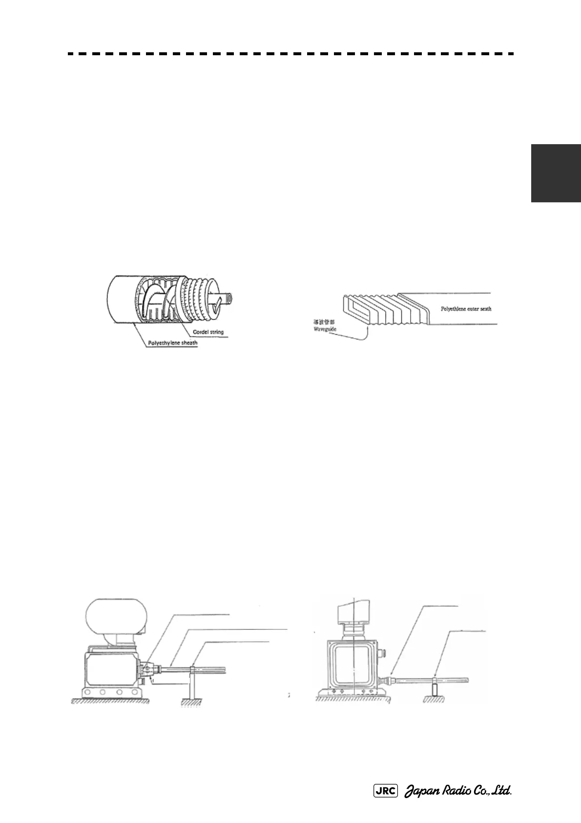
2.4.2 Routing coaxial cable and flexible waveguide
In the case of the three-unit system consisting of the display unit, transmitter-
receiver, and the scanner, use a Coaxial cable, shown in Fig 2-16, between the
transmitter-receiver and the scanner for the S-band, and use a Flexible waveguide,
shown in Fig 2-17, for the X-band.
1) Protecting coaxial cable and flexible waveguide
• Since cables and waveguides are hollow inside, when mounting them by using electric
wire bands, try not to fasten the bands too tightly around the cables and waveguides. If
they are fastened too tightly, the inside will become deformed or blocked, which may
cause the receiving sensitivity to decrease or the transmitter-receiver to be damaged.
• Stabilize the coaxial cable and the flexible waveguide by supporting members that are at
maximum intervals of 1000 millimeters. Mount a supporting member for the horizontal
wiring portion on the compass deck at an angle of 300 to 400 millimeters, and put a
protective metal cover over the cable and waveguide.
2) Preventing the connecting portion from becoming detached due to vibration
• Keep the connecting portion between the coaxial cable and the flexible waveguide and
the scanner's chassis, and provide supporting members, as shown in Fig 2-18 and Fig 2-
19, to prevent the connecting portion from becoming detached due to vibration.
• The distance from the connecting portion and the supporting member should be 400
millimeters for the S-band and 300 millimeters for X-band.
• If the distance from the connecting portion and the supporting member is longer than
the above distance, vibration may cause metal fatigue, resulting in the occurrence of
malfunction even if the connecting portion is not removed.
• For the cable end processing, refer to the procedure manual which comes with the cable.
Fig 2-16: Coaxial cable
Fig 2-17: Flexible waveguide
Fig 2-18: Position of S-band supporting member
Fig 2-19: Position of X-band supporting member
Coaxial tube ground
HF coaxial cable support clamp
C on necte r MPD W00297
Be straight from connecter to first support clamp
Waveguide Clamp
Scanner terminal
 Loading...


