ISO 9001, ISO 14001 Certified
OCT. 2019 Edition 4CODE No.7ZPRD0950
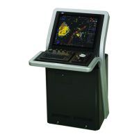
MARINE RADARMARINE RADAR
EQUIPMENTEQUIPMENT
JMRJMR
-
54105410
-
4X/6X/6XH4X/6X/6XH
JMRJMR
-
54255425
-
6XH/7X/9X6XH/7X/9X
JMRJMR
-
54305430
-
S
JMRJMR
-
54725472
-
S
JMRJMR
-
54825482
-
S/SHS/SH
Not use the asbestos
For further information,contact:
URL Head office : http://www.jrc.co.jp/eng/
Marine Service Department
1-7-32 Tatsumi, Koto-ku, Tokyo 135-0053, Japan
: tmsc@jrc.co.jp
:
+81-50-3786-9201
e
-
mail
One
-
call
INSTRUCTIONINSTRUCTION
MANUALMANUAL
JMR-5400 series MARINE RADAR EQUIPMENT INSTRUCTION MANUAL