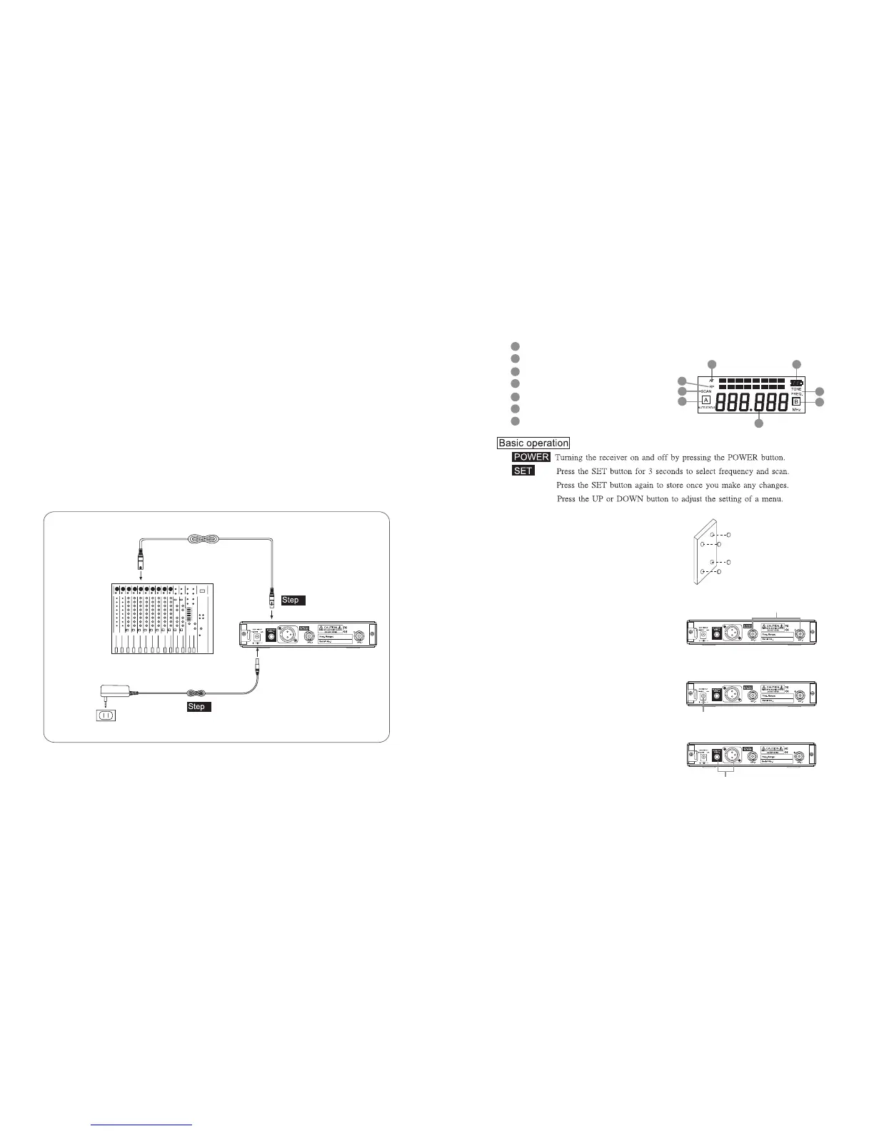
5. Preparing Procedures & Basic Operation
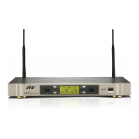
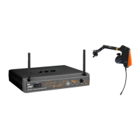
5-1 Receiver // US-901D US-9001D
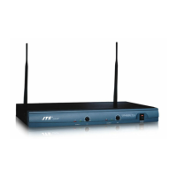
(1) Power output connector
Plug in one end of AC/DC adaptor cable to DC input socket in the rear panel of receiver, and
plug another end into an AC outlet.(Step 1)
(2) Audio Output Connector
Connect one end of the AF output cable to the AF output socket in the rear panel, then plug
another end to the “MIC IN” input socket of a mixer or amplier.(Step 2)
Receiver equipped with balanced XLR output and Unbalanced φ6.3mm output, choose the
proper way for use.
MIXER
AC/DC ADAPTOR
AC POWER SOCKET
AUDIO OUTPUT
DC INPUT
2
1
250
1856
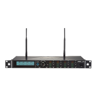
(3) LCD panel
AF signal
RF signal
Display for SCAN mode
Display for set FREQ. mode
Main display
Diversity display (A or B antenna)
Baery display for the transmier
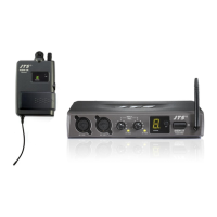
(4) Seing the rubber pad
Four self-adhesive rubber pads are provided
to ensure the stability.
ey are to be placed on the boom side of
the receiver.
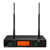
(5) Connecting the antennas
e user-friendly receiver antenna comes
with easy mount on socket for eortless
connection. Connect two antennas on the
back of the receiver and align them upward.
(6) Connecting the main unit
Plug in the DC connector on the back of the
receiver (DCV INPUT).
(7) Connecting the amplier/mixer console
Plug in the amplier/mixer console to the
(AF OUT UNBAL / BAL ) sockets.
66
68
65
67
70
64
69
65
66
69
67
69
68
7064
250
1856
250
1856
250
1856
ANT.1 / ANT.2
DCV INPUT
AF OUT UNBAL/BAL