Do you have a question about the JUMO AQUIS 500 CR and is the answer not in the manual?
Explains symbols for danger, caution, and electrostatic discharge.
Explains symbols for notes, footnotes, and action instructions.
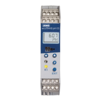
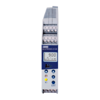
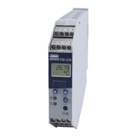
Overview of the device's purpose, application, and operational capabilities.
Visual representation of the device's inputs, outputs, and internal functions.
Details on the device's identification label and its key components.
Explanation of the order code structure and the meaning of each part.
Lists optional accessories available for purchase with their respective part numbers.
Guidelines for selecting a suitable mounting location and position for the device.
Step-by-step instructions for mounting the device onto a flat surface.
Instructions and diagram for installing the device into a control panel.
General safety and installation guidelines, emphasizing qualified personnel.
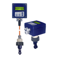
Detailed steps for connecting 2-electrode and 4-electrode conductivity cells.
Table detailing screw terminals and their corresponding rows for various device functions.
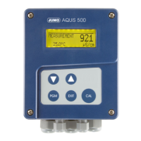
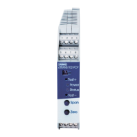
Identifies the device's LC display, control panel, and keys.
Explanation of the information and symbols displayed on the device's LC screen.
Flowchart illustrating navigation between operation modes and configuration levels.
Explains manual control and simulation of outputs for setup and troubleshooting.
Details on accessing and configuring the administrator settings and parameters.
A recommended procedure for quick and reliable device configuration.
Provides step-by-step examples for configuring the device for specific measurement applications.
Detailed procedure for calibrating the relative cell constant for enhanced measurement precision.
Procedure for calibrating the temperature coefficient for accurate temperature compensation.
A table listing common problems, their causes, and recommended solutions.
Procedures for testing the device's accuracy using reference liquids or calibrated devices.
Comprehensive specifications including inputs, temperature compensation, and electrical data.
Provides dimensions and instructions for cutting a panel for device installation.
| Category | Transmitter |
|---|---|
| Protection Class | IP65 |
| Communication Protocols | Modbus RTU |
| Display | LCD |
| Operating Temperature | -20 to +55 °C |
| Material | Stainless steel |