Do you have a question about the JUMO ecoTRANS Lf 03 and is the answer not in the manual?
Details the product's type designation and order code structure.
Specifies requirements for cable selection, fusing, and electrical connection.
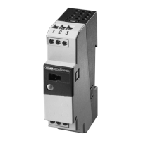
Illustrates the terminal connections for outputs and inputs.
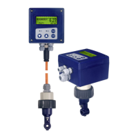
Explains the principle of electrolytic conductivity measurement and temperature dependence.
Describes the process of applying supply voltage and initial instrument behavior.
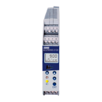
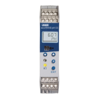
Details how the actual value is displayed in static or alternating mode.
Explains the instrument's operation arranged on different access levels.
Describes the function of the device's keys and navigation.
Illustrates the navigation flow between different user access levels.
Shows the parameter structure accessible at the operator level.
Displays the parameter structure accessible at the administrator level.
Outlines how user rights can be defined and modified at the enabling level.
Details the structure for accessing calibration functions.
Introduces the configurable input parameters for conductivity and temperature.
Details measurement ranges and nominal cell constants for conductivity input.
Details probe types, connection types, and filter constants for temperature input.
Introduces relay and open-collector output configurations.
Details switching functions for logic output 1.
Details switching functions for logic output 2.
Introduces the configurable analog output settings.
Details the type of standard signal for conductivity analog output.
Details the type of standard signal for temperature analog output.
Explains the need for calibration due to cell constant variations and temperature effects.
Details how to activate the calibration mode using keys or setup software.
Guides the user in selecting between calibrating temperature coefficient or relative cell constant.
Describes calibrating temperature coefficient using automatic measurements.
Explains how to calibrate temperature coefficient using manual temperature input.
Explains the general principles for calibrating the relative cell constant.
Explains response options (following/unchanged) during calibration.
Details how the output signal behaves in fault conditions (LOW/HIGH).
Describes output signal behavior when leaving the scaling range.
Explains manual operation for test/commissioning purposes.
Explains how the relay responds based on MAX LK or MIN LK settings.
Details manual operation for relay outputs.
Specifies relay response during calibration.
Explains the pulse function for relay output.
Details the relay response to faults.
Provides USP conductivity limits as a function of temperature.
Describes the USP pre-alarm function and its parameter.
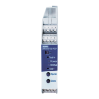
Explains the meaning of the device status LEDs.
Shows the display message for underrange conditions.
Shows the display message for overrange conditions.
Shows the display message for probe break conditions.
Shows the display message for short circuit conditions.
Explains the initialization of dependent parameters.
Shows the display message when the calibration timer expires.
Warns about electrical isolation issues when using the setup interface.
Details the JUMO PC setup software interface and navigation.
Covers conductivity input range, cell constants, lead compensation, and characteristic deviations.
Details temperature input types, ranges, compensation, and characteristic deviations.
Includes analog, relay, and open-collector output configurations and parameters.
Covers A/D converter, monitoring, power, temperature limits, and electrical connection.
Lists electrical safety, EMC, protection rating, housing, and mounting details.
| Brand | JUMO |
|---|---|
| Model | ecoTRANS Lf 03 |
| Category | Transmitter |
| Language | English |