Do you have a question about the JUMO dTRANS p02 and is the answer not in the manual?
Explains Danger and Caution symbols indicating potential harm to personnel or equipment.
Defines symbols for notes, references, footnotes, and actions for user guidance.
Introduction to the manual, contact details, warranty information, and ESD precautions.
Details the intended use of the pressure transmitter and its application in hazardous (Ex) areas.
Illustrates the layout and information present on the instrument's identification nameplate.
Details the coding system for product type designation, including basic type and extensions.
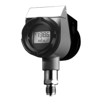
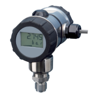
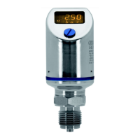
Presents diagrams with dimensions and labeled components of the pressure transmitter.
Provides dimensional drawings for non-flush pressure connection types like 512, 504, and 564.
Presents dimensional drawings for flush pressure connection types such as 604/606, 613/616, and 571.
Details technical specifications including range, shock/vibration resistance, protection, materials, and temperature limits.
Information on opening the cover flap and affixing function lists.
Instructions on system depressurization, site selection, and mounting considerations.
Illustrates the procedure for mounting the transmitter using its pressure connection.
Describes how to mount the transmitter using threads on the housing.
Details seals, tightening torque, and checks for pressure connection tightness.
Specifies seal requirements for using the device in Zone 0 hazardous areas.
Guides on electrical connections, including general notes and diagrams for terminals and connectors.
Provides a diagram and instructions for testing the transmitter's output signal.
Illustrates the connection setup for a HART modem to the pressure transmitter.
Shows the wiring diagram for connecting a HART communicator to the device.
Details the procedure and diagram for testing HART communication.
Covers general regulations and connection diagrams for hazardous area installations.
Describes the relationship between pressure and output signal, including range limits and display indicators.
Explains the automatic self-test sequence performed by the transmitter after power-on.
Provides step-by-step instructions for measuring absolute pressure in different media (gases, vapors, liquids).
Provides step-by-step instructions for measuring gauge pressure in different media (gases, vapors, liquids).
Explains the two-level operational structure (Display and Parameter levels) for the transmitter's functions.
Presents flowcharts detailing the sequence of operations using the keypad for display and parameter adjustments.
Explains how to navigate and view data such as pressure, temperature, and current at the display level.
Outlines parameter settings accessible through the keypad, including density correction, units, and output current.
Offers detailed explanations for parameters like peak-reading pointer, damping, zero adjustment, and characteristic settings.
Instructs on how to unscrew the bezel ring and housing cover to access the instrument's interior.
Details the procedure for rotating the LCD display and the instrument housing for optimal viewing.
Provides a troubleshooting guide with common errors, their possible causes, and recommended remedies.
Presents the official EC Type-Examination Certificate for the device, including its ATEX compliance.
Includes supplementary information and alterations related to the EC Type-Examination Certificate.
Contains the EU Declaration of Conformity for ATEX, confirming compliance with relevant directives.
A table summarizing the instrument's settings, including factory and customer configurations.
| Output Signal | 4-20 mA or 0-10 V |
|---|---|
| Response Time | < 1 s |
| Housing Material | Plastic |
| Protection Class | IP65 |
| Process connection | G 1/2" |
| Electrical connection | M12 connector |
| Media temperature | -40 to +125 °C |
| Ambient temperature | -20 to +60 °C |
| Long-term stability | ≤ 0.1% per year |
| Operating temperature | -20 to +60 °C |