Do you have a question about the JUMO dTRANS p20 and is the answer not in the manual?
Describes warning and informational symbols used in the manual for safety.
Discusses risks associated with hazardous materials used as a medium.
Explains the various applications and usage scenarios for the device.
Details device usage in hazardous (Ex) areas and for functional safety applications.
Lists essential documents included with the device for operation and calibration.
Details optional hardware and software for enhanced device functionality and connectivity.
Explains the various components and information found on the device's nameplate.
Details the structure of the order code and the meaning of each configurable parameter.
Lists various accessories, such as cables and holders, for the device.
Describes the software tools available for configuration and management of the device.
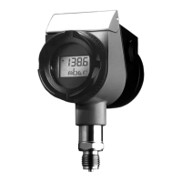
Presents diagrams and dimensions for various device configurations and housings.
Illustrates and details various types of process connections available for the device.
Details general parameters like reference conditions, voltage supply, and display characteristics.
Details input ranges, overload, and burst pressures for relative and absolute pressure measurements.
Covers analog output types, burden, and voltage supply requirements for various versions.
Describes materials, housing types, electrical connections, and overall weight of the device.
Details admissible operating temperatures, humidity, vibration, EMC compliance, and protection types.
Details accuracy parameters including non-linearity, hysteresis, and long-term stability.
Lists relevant certifications like ATEX, DNV-GL, EAC, and SIL, along with their inspection basis.
Covers safety warnings and general guidance before starting the mounting process.
Explains how to unscrew the front ring or case lid to access internal parts.
Provides instructions on how to rotate the LCD display module in 90° steps.
Details the procedure for rotating the housing by ±160° for proper alignment.
Guides on connecting the device to the pressure port, including seal selection and tightening torques.
Explains the steps for pressurizing the device for relative or absolute pressure measurement.
Illustrates the use of a bracket for mounting the device on walls or pipes.
Guides on setting up the device for level measurement, with or without a pressure separator.
Offers critical information and handling precautions for systems employing diaphragm seals.
Outlines the procedures for installing the device safely in potentially explosive environments.
Covers crucial safety warnings and general guidance for the installation process.
Provides instructions for installing the device when using a cable gland for connection.
Details the terminal assignments for voltage, output, HART, and ground connections.
Covers initial operation and testing procedures after the device has been installed.
Provides instructions for installing the device using an M12 connector.
Details critical electrical connection procedures and safety requirements for Ex-rated areas.
Provides a detailed connection diagram for safe installation in potentially explosive areas.
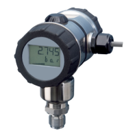
Describes the elements shown on the device's LCD display, including measured values and units.
Covers device operation via the physical rotary knob or the external setup program.
Explains the two-level operational structure: display level and parameter level.
Describes how to interpret information shown on the display level, including measured values.
Details how to access and modify device parameters at the parameter level.
Presents a diagram illustrating the internal data flow and parameter relationships.
Explains key configuration parameters such as density, units, and measuring range settings.
Guides on configuring level measurement using pressure specifications for tank filling.
Details level measurement setup without pressure specifications, for use with or without diaphragm seals.
Lists common errors, their possible causes, and recommended remedies for troubleshooting.
Provides device-specific information relevant to HART communication protocols.
Lists and explains the variable codes used for HART communication and device data.
Lists and describes universal and common practice commands for interacting with the device via HART.
Details commands used to configure and manage the device's burst mode operation.
Covers telegram length, operating modes, and write protection features.
| Brand | JUMO |
|---|---|
| Model | dTRANS p20 |
| Category | Transmitter |
| Language | English |