6 Installation
46
NOTE!
Connecting the HART® communicator or the HART® modem is optional.
A minimum burden must be present on the signal circuit in order to facilitate error-free communication,
see the previous pages.
The burden is usually already integrated when using input isolating amplifiers.
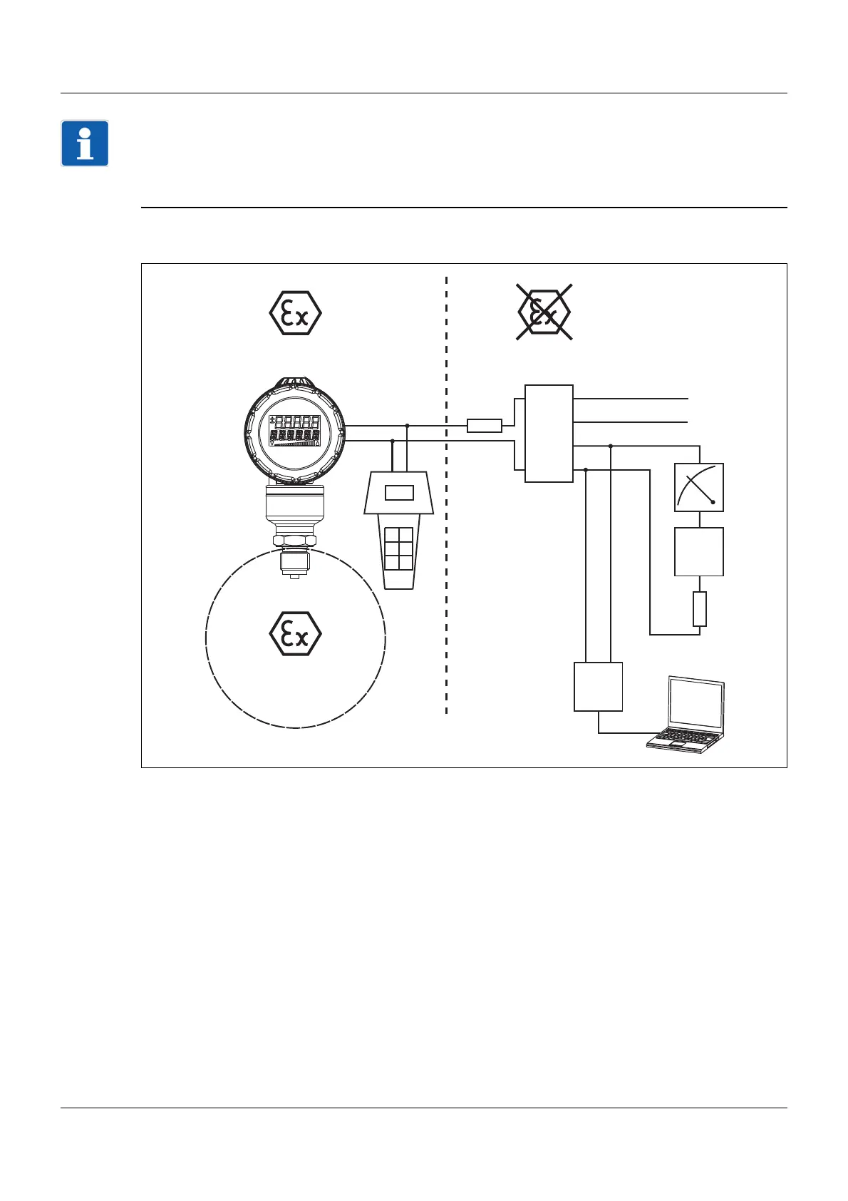
6.4.1 Connection diagram "Ex"
(1) Potentially explosive area zone 0/20
(2) Potentially explosive area zone 1/21
(3) Non-potentially explosive area
(4) Burden for HART® ≤ (U
B
-12 V) ÷ 0.022 A;
additional: min. 250 Ω, max. 1100 Ω
The current limiting resistor integrated in the power supply unit must be included in this calculation.
(5) Power supply unit with an isolating converter for connecting explosion-proof transmitters
(6) Indicating device or recorder, controller, PLC, etc.
(7) Further devices
(8) Burden for HART® min. 250 Ω, max. 1100 Ω
The current limiting resistor integrated in the power supply unit must be included in this calculation.
(9) HART® modem
(10) PC or notebook
(11) HART® communicator, intrinsically safe
+
+
-
+
-
-
(2)(3)
(4)
(5)
(1)
(6)
(7)
(8)
(9)
(10)
(11)
 Loading...