Do you have a question about the JUMO DELOS SI and is the answer not in the manual?
Explains danger symbols and their meanings for personal injury or damage.
Explains the information symbol for important product details.
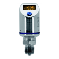
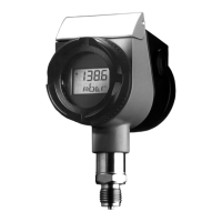
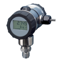
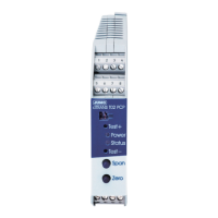
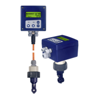
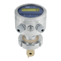
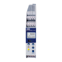
Provides a general overview of the instrument's function, features, and available outputs.
Describes the information found on the instrument's nameplate, including type and serial number.
Illustrates the functional components and signal flow of the JUMO DELOS SI instrument.
Lists the various options and codes for configuring and ordering the instrument.
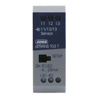
Lists available accessories for the instrument, such as interface cables and tools.
Mentions the setup software required for instrument configuration.
Provides essential safety guidelines and procedures for electrical installation.
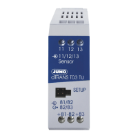
Details the pin assignment and color coding for the M12 x 1 round plug.
Specifies terminal connections for a single PNP switching output.
Specifies terminal connections for dual PNP switching outputs.
Details terminal connections for analog outputs combined with PNP switching.
Covers crucial safety precautions and general mounting advice for the instrument.
Explains how to rotate the display image via software for better readability.
Describes how to rotate the instrument housing using a combination tool.
Provides physical dimensions and outlines for different instrument types.
Details various non-front-flush process connection types and their dimensions.
Outlines front-flush process connection options (G 3/4) and their specifications.
Details process connections like G 1, taper sockets, and clamp types.
Shows dimensions for small flange, tank connection, and JUMO PEKA connections.
Identifies the protective screw and hexagon socket for operating the device.
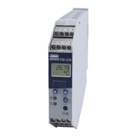
Explains the Liquid Crystal display behavior in measurement and setting modes.
Illustrates the navigation flow through the instrument's menu levels.
Details input parameters like pressure unit, offset, and damping.
Covers parameters for signal type, scaling, and error signal for analog outputs.
Explains settings for switching function, point, reset, hysteresis, and delay.
Covers parameters for the second switching output.
Details display position, unit, and software version display.
Provides a checklist for reliable and efficient instrument configuration.
Explains the procedure to unlock the instrument using a factory code.
Guides on cancelling operations and selecting the measurement unit (Uni.P).
Lists measuring ranges and their corresponding display and setting values.
Details setting the zero point offset and filter time constant.
Guides on setting the output signal type and scaling.
Details setting the starting and final values for analog output scaling.
Covers setting the error signal and configuring switching functions (hysteresis/window).
Guides on setting the switching point, reset point, and switching delay.
Covers setting the display orientation and the unit of displayed values.
Instructions to view the operating device and signal stage software versions.
Guides on automatic zero point adjustment for relative pressure instruments.
Explains manual adjustment of the zero point offset via setup program.
Describes the capabilities of the PC setup software for instrument configuration.
Provides step-by-step instructions on how to launch the setup program.
Lists common errors, their causes, and recommended troubleshooting measures.
Provides general specifications like reference conditions, display, and operation.
Details linearity, accuracy, stability, and capacity for various measuring ranges.
Specifies technical details for analog and switching outputs, including current and voltage.
Lists materials, seals, and dimensions of mechanical components and process connections.
Details permissible temperatures, humidity, vibration, and shock resistance.
Covers EMC requirements, interference emission/immunity, and protection ratings.
Specifies voltage supply, power consumption, and electrical connection details.
| Protection Type | IP67 |
|---|---|
| Storage Temperature | -40 to +85 °C |
| Material | Stainless steel |
| Output Signal | 4 to 20 mA |
| Power Supply | 12-30 V DC |
| Communication Protocol | HART |
| Accuracy | ±0.5% FS |
| Process Connection | G 1/2 |
| Electrical Connection | M12 connector |